247
7647H–AVR–03/12
Atmel ATmega16/32/64/M1/C1
• Bit 6– ADSC: ADC Start Conversion Bit
Set this bit to start a conversion in single conversion mode or to start the first conversion in free
running mode.
Cleared by hardware when the conversion is complete. Writing this bit to zero has no effect.
The first conversion performs the initialization of the ADC.
• Bit 5 – ADATE: ADC Auto trigger Enable Bit
Set this bit to enable the auto triggering mode of the ADC.
Clear it to return in single conversion mode.
In auto trigger mode the trigger source is selected by the ADTS bits in the ADCSRB register.
See Table 18-7 on page 248.
• Bit 4– ADIF: ADC Interrupt Flag
Set by hardware as soon as a conversion is complete and the Data register are updated with the
conversion result.
Cleared by hardware when executing the corresponding interrupt handling vector.
Alternatively, ADIF can be cleared by writing it to logical one.
• Bit 3– ADIE: ADC Interrupt Enable Bit
Set this bit to activate the ADC end of conversion interrupt.
Clear it to disable the ADC end of conversion interrupt.
• Bit 2, 1, 0– ADPS2, ADPS1, ADPS0: ADC Prescaler Selection Bits
These 3 bits determine the division factor between the system clock frequency and input clock of
the ADC.
The different setting are shown in Table 18-6.
18.9.3 ADC Control and Status Register B– ADCSRB
• Bit 7 – ADHSM: ADC High Speed Mode
Writing this bit to one enables the ADC High Speed mode. Set this bit if you wish to convert with
an ADC clock frequency higher than 200KHz.
Clear this bit to reduce the power consumption of the ADC when the ADC clock frequency is
lower than 200KHz.
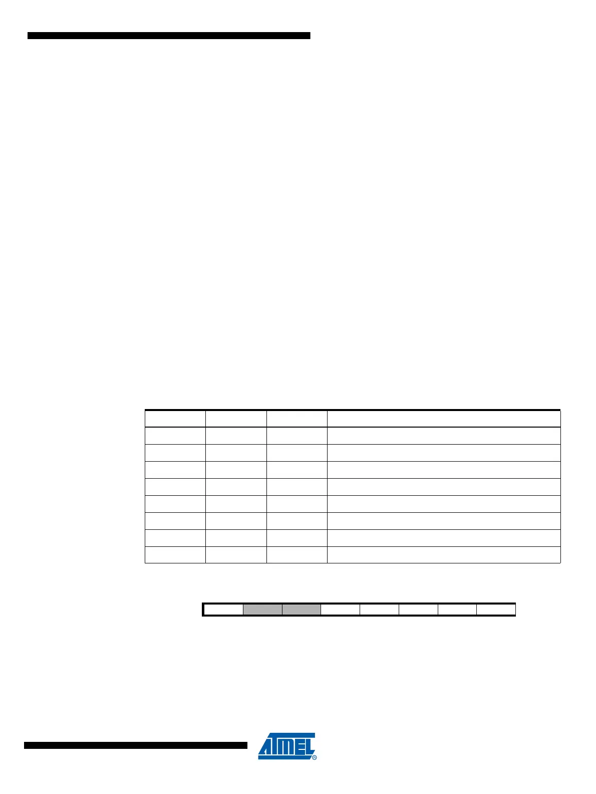
Table 18-6. ADC Prescaler Selection
ADPS2 ADPS1 ADPS0 Division Factor
0002
0012
0104
0118
10016
10132
11064
111128
Bit 76543210
ADHSM ISRCEN AREFEN - ADTS3 ADTS2 ADTS1 ADTS0 ADCSRB
Read/Write R/W R/W R/W R R/W R/W R/W R/W
Initial Value 00000000