252
7647H–AVR–03/12
Atmel ATmega16/32/64/M1/C1
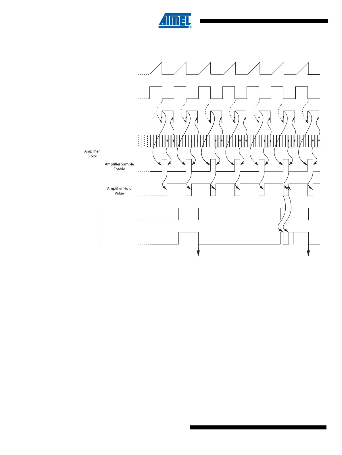
Figure 18-16. Amplifier synchronization timing diagram
ADSC is set when the amplifier output is changing due to the amplifier clock
switch
In order to have a better understanding of the functioning of the amplifier synchronization, a tim-
ing diagram example is shown Figure 18-15.
It is also possible to auto trigger conversion on the amplified channel. In this case, the conver-
sion is started at the next amplifier clock event following the last auto trigger event selected
thanks to the ADTS bits in the ADCSRB register. In auto trigger conversion, the free running
mode is not possible unless the ADSC bit in ADCSRA is set by soft after each conversion.
Valid sample
Signal to be
measured
AMPLI_clk
(Sync Clock)
CK ADC
PSCn_ASY
PSC
Block
ADSC
ADC
Activity
ADC
ADC
Sampling
ADC
Co n v
ADC
Sampling
ADC
Co n v
ADC
Sampling
Aborted
ADC Result
Ready
ADC Result
Ready