311
7647H–AVR–03/12
Atmel ATmega16/32/64/M1/C1
25.8.14 Reading the Calibration Byte
The algorithm for reading the Calibration byte is as follows (refer to “Programming the Flash” on
page 305 for details on Command and Address loading):
1. A: Load Command “0000 1000”.
2. B: Load Address Low Byte, 0x00.
3. Set OE
to “0”, and BS1 to “1”. The Calibration byte can now be read at DATA.
4. Set OE
to “1”.
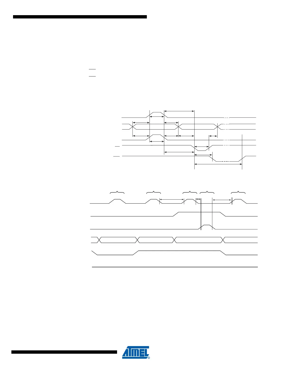
25.8.15 Parallel Programming Characteristics
Figure 25-7. Parallel Programming Timing, Including some General Timing Requirements
Figure 25-8. Parallel Programming Timing, Loading Sequence with Timing Requirements
(1)
Note: 1. The timing requirements shown in Figure 25-7 (i.e., t
DVXH
, t
XHXL
, and t
XLDX
) also apply to load-
ing operation.
Data & Contol
(DATA, XA0/1, BS1, BS2)
XTAL1
t
XHXL
t
WLWH
t
DVXH
t
XLDX
t
PLWL
t
WLRH
WR
RDY/BSY
PAGEL
t
PHPL
t
PLBX
t
BVPH
t
XLWL
t
WLBX
t
BVWL
WLRL
XTAL1
PAGEL
t
PLXH
XLXH
t
t
XLPH
ADDR0 (Low Byte) DATA (Low Byte) DATA (High Byte) ADDR1 (Low Byte)
DATA
BS1
XA0
XA1
LOAD ADDRESS
(LOW BYTE)
LOAD DATA
(LOW BYTE)
LOAD DATA
(HIGH BYTE)
LOAD DATA
LOAD ADDRESS
(LOW BYTE)

 Loading...


