58
7647H–AVR–03/12
Atmel ATmega16/32/64/M1/C1
Notes: 1. When the BOOTRST Fuse is programmed, the device will jump to the Boot Loader address at
reset, see “Boot Loader Support – Read-While-Write Self-Programming
ATmega16/32/64/M1/C1” on page 279.
2. When the IVSEL bit in MCUCR is set, Interrupt Vectors will be moved to the start of the Boot
Flash Section. The address of each Interrupt Vector will then be the address in this table
added to the start address of the Boot Flash Section.
3. These vectors are not used by ATmega32/64C1.
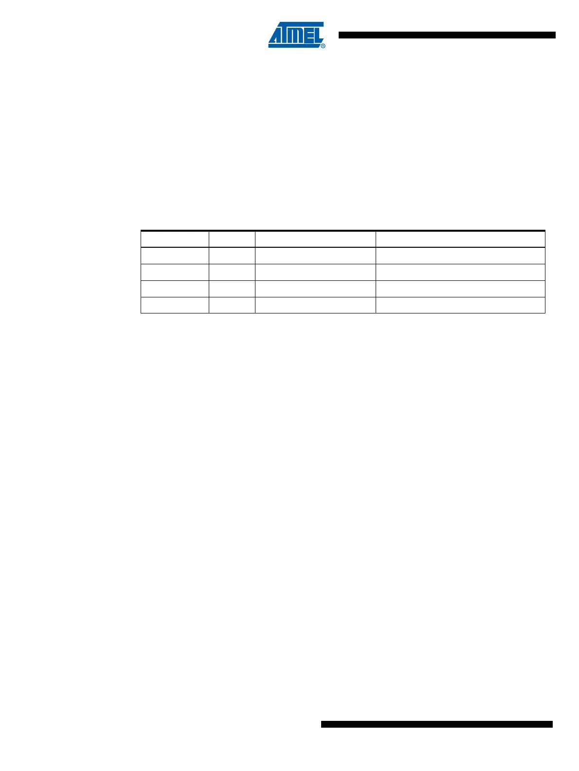
Table 8-2 shows reset and Interrupt Vectors placement for the various combinations of
BOOTRST and IVSEL settings. If the program never enables an interrupt source, the Interrupt
Vectors are not used, and regular program code can be placed at these locations. This is also
the case if the Reset Vector is in the Application section while the Interrupt Vectors are in the
Boot section or vice versa.
Note: 1. The Boot Reset Address is shown in Table 24-4 on page 283. For the BOOTRST Fuse “1”
means unprogrammed while “0” means programmed.
The most typical and general program setup for the Reset and Interrupt Vector Addresses in
ATmega16/32/64/M1/C1 is:
Address Labels Code Comments
0x000 jmp RESET ; Reset Handler
0x002 jmp ANA_COMP_0 ; Analog Comparator 0 Handler
0x004 jmp ANA_COMP_1 ; Analog Comparator 1 Handler
0x006 jmp ANA_COMP_2 ; Analog Comparator 2 Handler
0x008 jmp ANA_COMP_3 ; Analog Comparator 3 Handler
0x00A jmp PSC_FAULT ; PSC Fault Handler
0x00C jmp PSC_EC ; PSC End of Cycle Handler
0x00E jmp EXT_INT0 ; IRQ0 Handler
0x010 jmp EXT_INT1 ; IRQ1 Handler
0x012 jmp EXT_INT2 ; IRQ2 Handler
0x014 jmp EXT_INT3 ; IRQ3 Handler
0x016 jmp TIM1_CAPT ; Timer1 Capture Handler
0x018 jmp TIM1_COMPA ; Timer1 Compare A Handler
0x01A jmp TIM1_COMPB ; Timer1 Compare B Handler
0x01C jmp TIM1_OVF ; Timer1 Overflow Handler
0x01E jmp TIM0_COMPA ; Timer0 Compare A Handler
0x020 jmp TIM0_COMPB ; Timer0 Compare B Handler
0x022 jmp TIM0_OVF ; Timer0 Overflow Handler
0x024 jmp CAN_INT ; CAN MOB,Burst,General Errors Handler
0x026 jmp CAN_TOVF ; CAN Timer Overflow Handler
0x028 jmp LIN_TC ; LIN Transfer Complete Handler
0x02A jmp LIN_ERR ; LIN Error Handler
0x02C jmp PCINT0 ; Pin Change Int Request 0 Handler
Table 8-2. Reset and Interrupt Vectors Placement in ATmega16/32/64/M1/C1
(1)
BOOTRST IVSEL Reset Address Interrupt Vectors Start Address
1 0 0x000 0x001
1 1 0x000 Boot Reset Address + 0x002
0 0 Boot Reset Address 0x001
0 1 Boot Reset Address Boot Reset Address + 0x002