12. Convergence
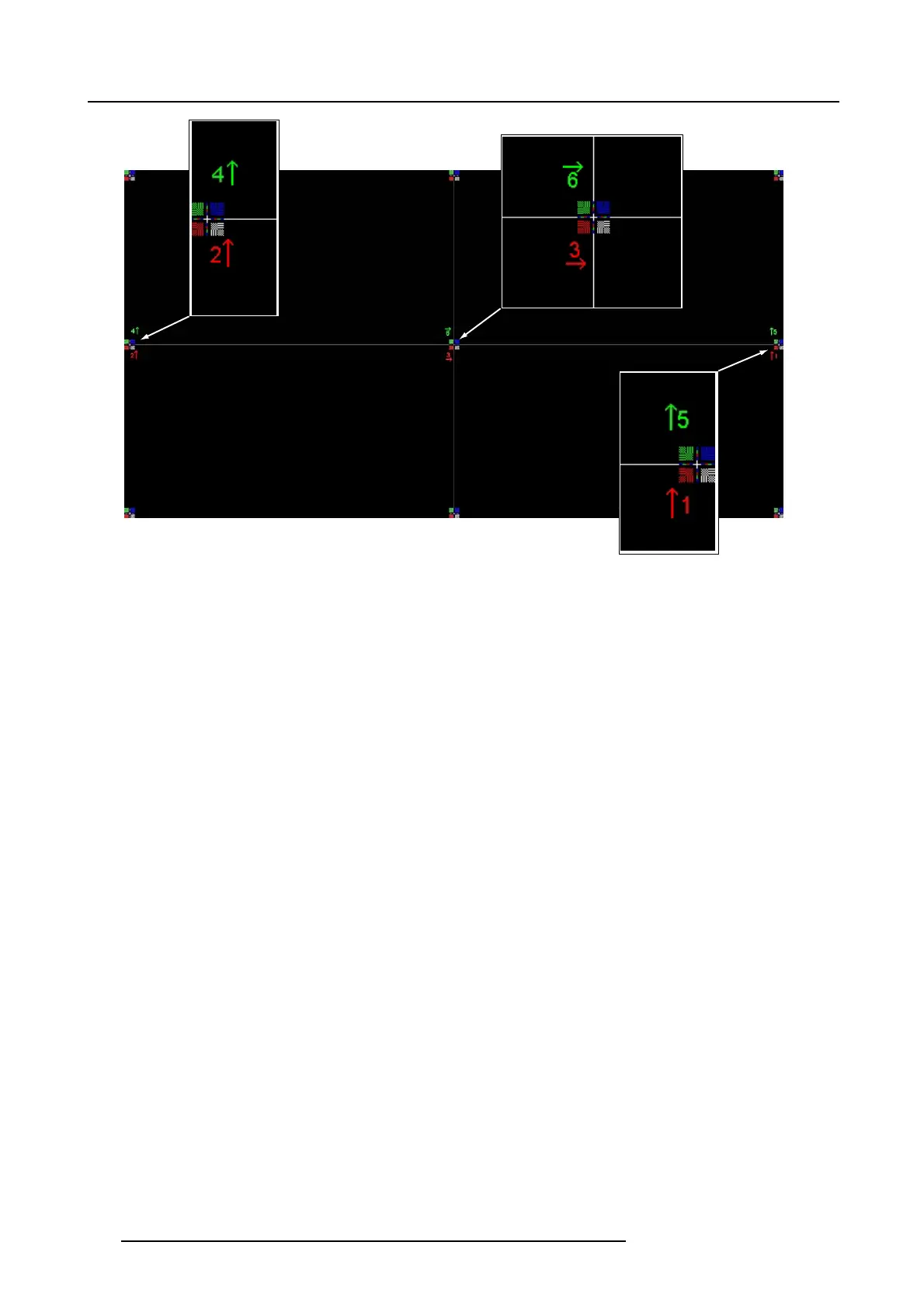
Image 12-6
Convergence test pattern
Work Instructions:
• GREEN and RED D MD ’s are to be adjusted with reference to the BLUE dmd.
• Each adjustment allows for approx imately 10 pixels max
imum displaceme nt to either side of the nominal BLUE position
• Rotation is lim ited to approximately +/- 5pixels on the left screen flank and +/- 5 pixels on the right screen flank
• One turn of an adjustment screw relates to an approx. 5-pixel displacement on the screen.
Take Care:
• In rare cases it can happen that the nominal dm d position falls within a dead zone, where the mechanism changes from a
pushing to a pulling function. This dead z one is due to inherent tolerances within the mec hanism . A pproximately 2 turns a re
required to get out of the dead zone. If it so
happens that the nominal position of an adjustment falls within this dead zone,
it is preferable to continue screwing through the dead zone for an other 2 turns. Then return to the required nominal position.
The dead zone should now be displaced away from the required end pos ition. The DMD is now securely held in the nominal
position.
• Each adjustment is lim ited to approximately 10 pixels displacement. DO N OT try to force the adjustment beyond this point. The
system has an end of travel in both directions, but with excessive force on e could cause damage.
118
R59770495 DP2K-23B 30/04/2010

 Loading...


