3. Physical installation
3.4 Connecting the projector with the p ower net
WARNING: The total electrical installation should be p rotected by an appropriate rated and readily accessi-
ble disconnect switch, circuit breakers and ground fault current interrupters. The installation shall be done
according to the local electrical installation codes.
WARNING: M ake sure that the voltage range o f projector matches w ith the voltage of the local power net.
CAUTION: The cross-sectional area of the conductors in the Power Supply Cord shall be not less than 4 mm
2
or AWG 10
Necessary tools
• Flat torque screw driver
• Adjustable wrench
Necessary parts
•Certified power supply cord 4 .0 mm ², 10AWG, min. 3 00V, diameter between 11 mm and 21 mm
• Circuit breaker max imum 40A
How to connect
1. R emove the back cover.
2. R emove the power input c over.
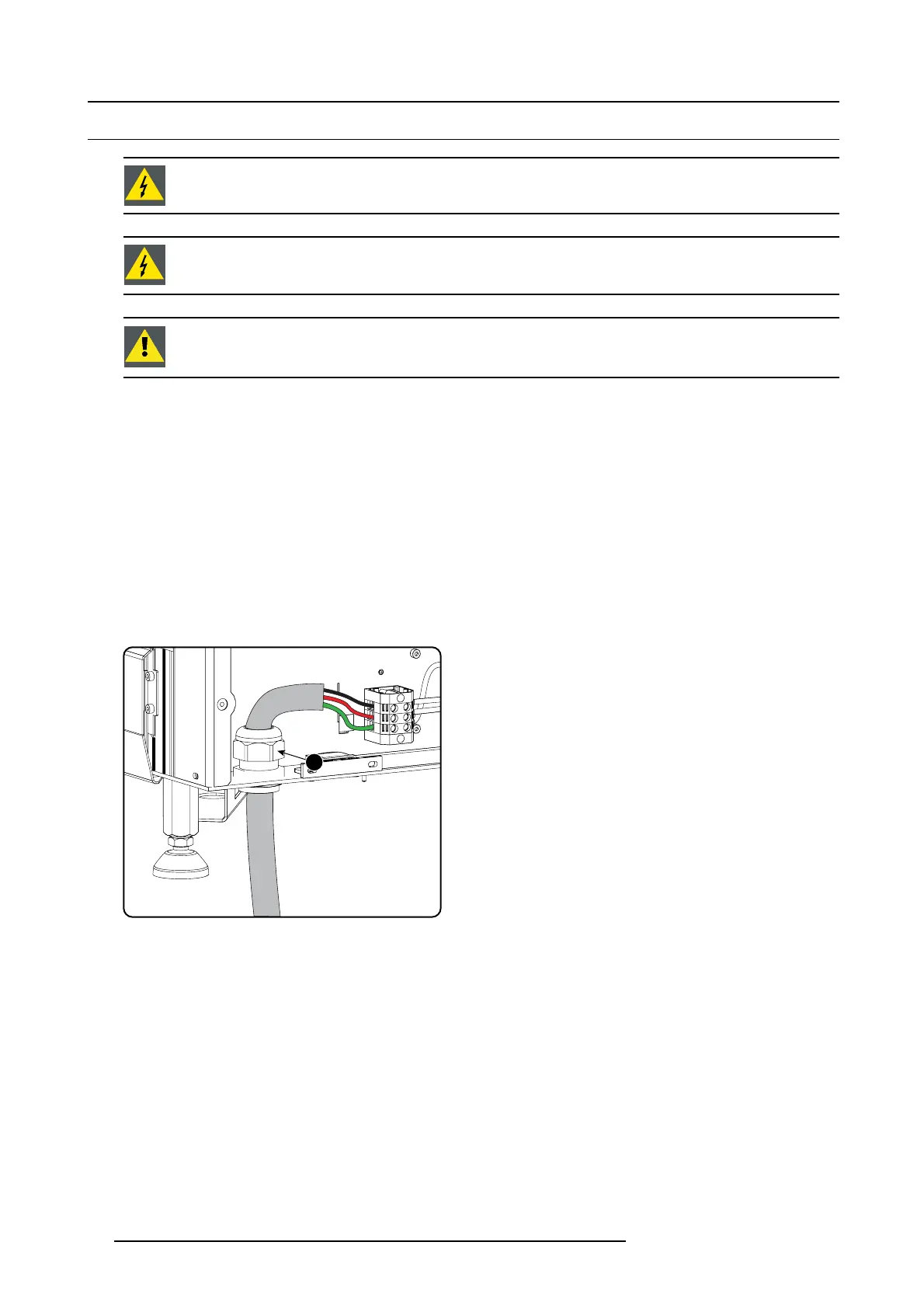
3. Loosen the cable g land fixation ring (1 ).
Note: The cable gland ( 1) is specified for cables with a diameter between 11mm and 21m m.
1
Image 3-9
Power cable connection
4. Push the s tripped power supply cable through the cab
le gland. Whe n using a flexible power cord, ma ke sure that each conductor
end is provided with an end s leeve.
Fix the cable in the cable gland by s ecuring ring 1 w ith an adjustable wrench.
5. C onnect the power cord with the terminal barriier strip. Use a flat torque screw driver set to 2Nm.
Always connect th e ground wire (PE) with the c onnector indicated with PE on the terminal bar rier s trip.
Warning: Always connect first the PE wire .
6. R einstall the power connection cov er and the back cover.
24
R59770495 DP2K-23B 30/04/2010

 Loading...


