3. Input & Communication
3. INPUT & C OMMU NICATION
Overview
• Introduction
• Connection Panel
• Making connections
• Connector specifications
• Control interfaces
• LED and Button indic ation chart
3.1 Introduction
General
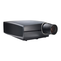
The Input & C ommunication features of the p rojector consists of a local keypad and a communication panel situated at the left side,
and a connection panel (sources and c ontrol connections) located at the back side.
1 2
Image 3-1
1 local keypad and a communication panel
2 connection panel
3.2 Connection Panel
General
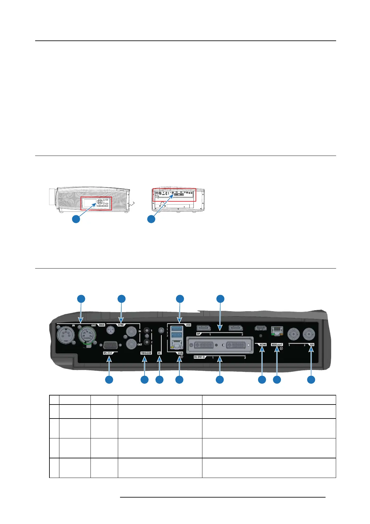
Projector sources and control connections are located at the back o f the pro jector.
1 3 6 8
2 4 5 7 9 1110 12
Image 3-2
Nb. N ame Pcs Description Purpose
1DMX
IN/OUT
2
DMX 512 input / DMX 512 output For Projector Control
2
RS-232
1 9–pin DB9 connector
For Projector Control. Allows for wired remote control and
monitoring of many projector functions used in installation
environments
3
Sync
3
BNC Sync Port IN/OUT; Bidirectional
mini-DIN (1x 3D sync O ut, and 2x
Sync In/Out)
For Projector Control. This is mainly used in multiple
projector installations with r equirement of synchronization
between the units
4 Trigger 2 12VDC - 0,5A (6W) For Controlling Peripherals, like motorized screens,
curtains etc. Give 12V o utput when projector are s witched
onSee also the note below.
R5906852 F80 SERIES 21/09/2017 17
 Loading...