8. GUI – Installation
1
2
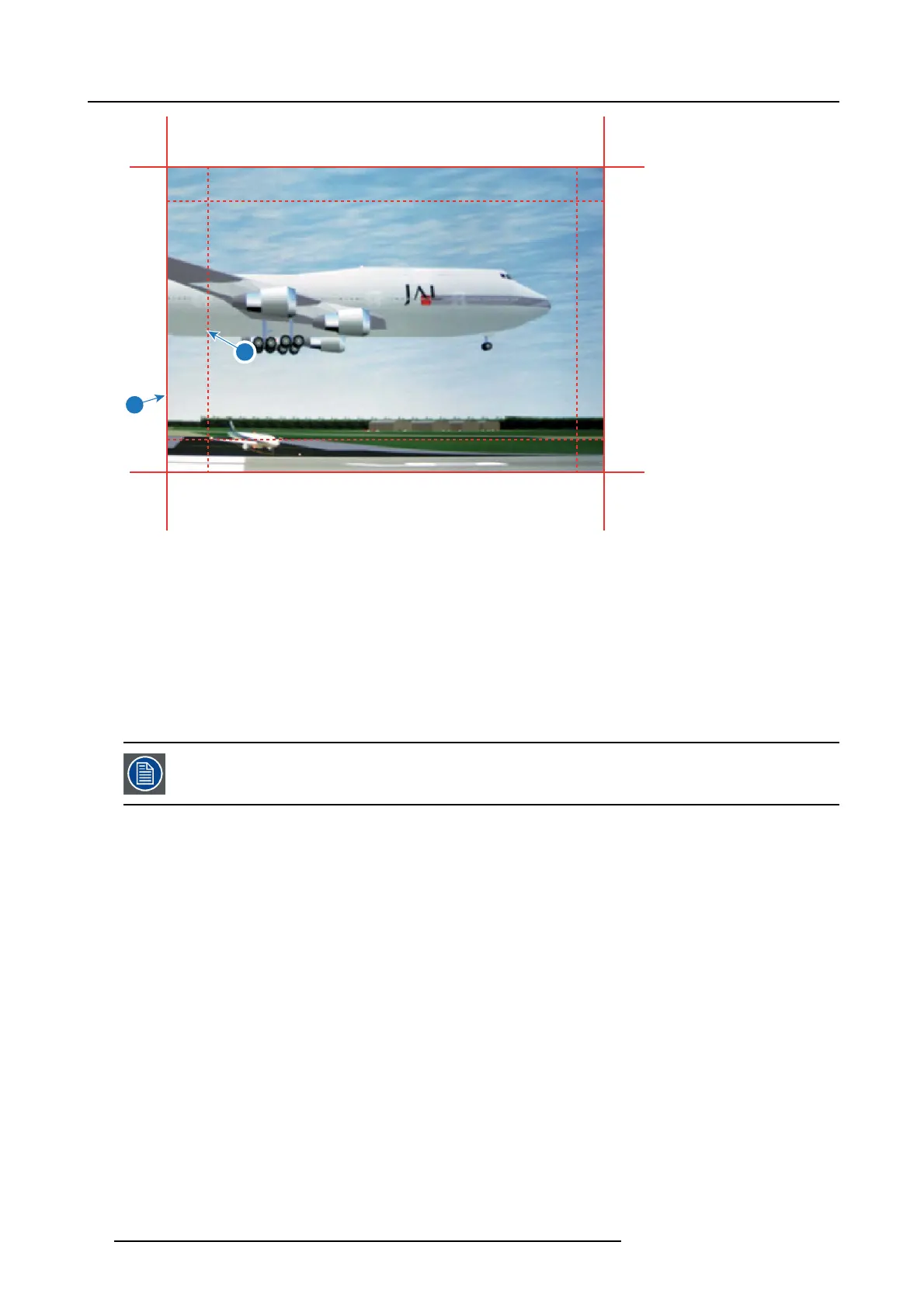
Image 8-25
1 Start position (offset)
2 Blending width
5. First select an offset and click M enu selection to activate the selection.
Use the arrow keys to c hange the value (the start position of the blending)
Repeat for the other edges if necessary.
6. Select the height or width and setup a size value.
Repeat for the other edges if necessary.
The value will range from 0 to 1.0 (linear to S-curved), w ith a default value of 0.5.
Example of the use o f blending
When projecting an im age with 2 projectors, there is always an sm all overlap that s hould be co rrected by using the blending function.
In order to obtain a satisfying result for the Bl
end function, the overlap / Blend z one are recommended to be
at least 10% of the picture width.
The basic principle is that the ov erlap setup in the source shall correspond with the blend w idth setup for the projector. That means
that if the over lap zone for the source is set to 500 pixels, the width of the blend zone for the projector also mus t be set to 500 pixels.
First step is to align the image from the projectors as ac curate as pos sible in a mec hanical way, meaning without any optical correc-
tions. At the same time, es tablish an overlap in the pictures between the two s creens.
Then adjust the rem aining irregularities by us ing the shift and warp features in the projectors to obtain the las t fine tuning of the
alignment.
Enable blending and activate Show lines.
First se t the blending w idth for the right edg
eofthefirst projector. Enter a width value equal to the ove rlap area (width1).
Repeat for the left edge of the second projector.
Adjust the offset to cut the image on each side (masking).
52
R5906852 F80 SERIES 21/09/2017
 Loading...