380 9424200994 Rev N
Protection, Voltage,
Overexcitation
Target Configuration, Targets
Alarm Configuration, Alarms
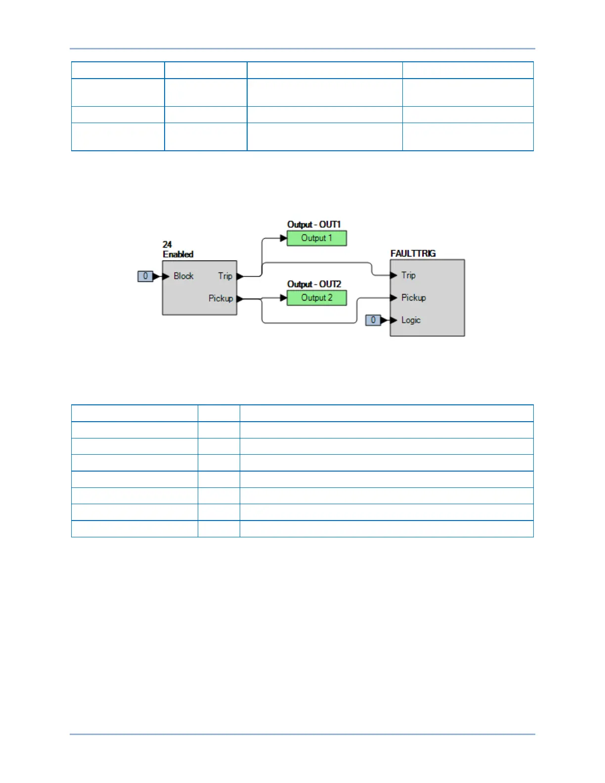
Step 2: Use BESTCOMSPlus to configure the BESTlogicPlus programmable logic shown in Figure 276.
• Blocking is disabled.
• OUT1 closes for 24 Trip.
• OUT2 closes for 24 Pickup.
Figure 276. BESTlogicPlus Settings
Step 3: Use BESTCOMSPlus to open the Protection, Voltage, Overexcitation (24) screen and send the
test settings in Table 126 to the BE1-11g.
Table 126. Alarm and Inverse Time Pickup Test Settings
Sets Inverse Time Pickup at 105% of nominal (2.10 V/Hz)
Sets Inverse Time Dial at minimum
Sets Inverse Reset Dial at minimum
Disables Definite Timer 1 Pickup
Disables Definite Timer 2 Pickup
Sets Alarm at 102.5% of nominal (2.05 V/Hz)
Step 4: Prepare to monitor the operation of the 24 Alarm and Trip functions. Alarm operation can be
verified by monitoring the Major Alarm LED on the protection system's front panel. Operation of
the 24 Trip can be verified by monitoring OUT1.
Step 5: Connect a three-phase, 100 Vac/50-Hz or 120 Vac/60-hertz voltage source (depending on
user's nominal frequency) to Terminals C13 (A-phase), C14 (B-phase), C15 (C-phase), and
C16 (neutral).
Step 6: Apply A-phase voltage at nominal frequency and slowly increase until the Major Alarm LED
lights (V/H PU x Freq x % Alarm = PU) and record the alarm pickup. Slowly decrease the A-
phase voltage until the Major Alarm LED extinguishes and record the dropout.
Step 7: Apply A-phase voltage at nominal frequency and slowly increase until OUT2 closes (V/H Trip x
Freq = PU) and record the pickup. Verify that there is a 24 target on the front-panel display.
Slowly decrease the A-phase voltage until OUT2 opens and record the dropout.
Step 8: (Optional.) Repeat steps 1 through 7 for higher and lower alarm and pickup settings.
Step 9: (Optional.) Repeat steps 1 through 8 for frequencies other than nominal.
Overexcitation (24) Test BE1-11g
 Loading...


