382 9424200994 Rev N
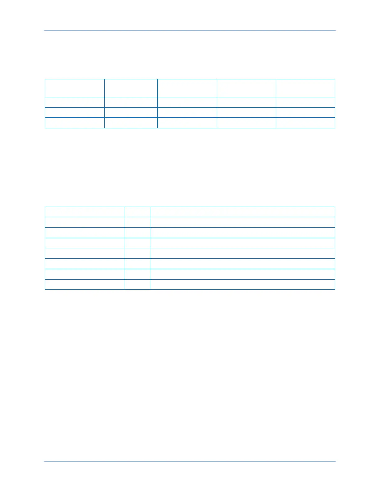
Step 3: All inverse timing tests are based on % of nominal Volts/Hertz (1 PU value). Refer to the Time
Curve Characteristics chapter. Step the A-phase voltage to a value that equals the V/Hz % of
nominal shown in Table 129 for Time Dial 0.5. Measure the time between the increase of
voltage and the closure of OUT1. Record the results.
Table 129. Inverse Time Verification Trip Times
Step Voltage Time Dial 0.5 Time Dial 1.0 Time Dial 2.0
Step 4: Repeat the test for Time Dial 1.0 and 2.0. Record the results.
Step 5: (Optional.) Repeat steps 1 through 4 for the B-phase and C-phase voltage inputs.
Step 6: (Optional.) Repeat steps 1 through 5 for settings group 1, 2, and 3.
Inverse Time Reset Verification
Step 1: Use BESTCOMSPlus to open the Protection, Voltage, Overexcitation (24) screen and send the
test settings in Table 130 to the BE1-11g.
Table 130. Inverse Time Reset Verification Test Settings
Sets Inverse Time Pickup at 105% of nominal (2.10 V/Hz)
Sets Inverse Time Dial at 0.5
Sets Inverse Reset Dial at 0.2
Disables Definite Timer 1 Pickup
Disables Definite Timer 2 Pickup
Step 2: Connect and apply 120 Vac, three-phase, 60-hertz voltage source to Terminals C13 (A-phase),
C14 (B-phase), C15 (C-phase), and C16 (neutral).
Step 3: Step the A-phase voltage to 144 V (120% of nominal V/Hz). OUT1 should close in
approximately 12.5 seconds. Remove the test voltage (step back down to 120 V) and reapply
(step back up to 144 V) after 5 seconds has elapsed. Measure the time from when the test
voltage is reapplied until OUT1 closes. Record the result.
Note: With a Reset Time Dial setting of 0.2, the total time to reset, after trip is removed, will be
approximately 10 seconds. (See the Overexcitation (24) Protection chapter for more details.)
Reapplying the test voltage after 5 seconds will yield a trip time of approximately ½ its original
value or 6.25 seconds for Trip Time Dial 0.5 verifying that the reset time delay is working.
Step 4: Repeat step 3 for Trip Time Dial 1.0 and 2.0 (½ trip time is approximately 12.5 seconds for Time
Dial 1.0, and 25 seconds for Time Dial 2.0. (Still reapply voltage after 5 seconds as reset time
dial is still 0.2.) Record the results.
Step 5: (Optional.) Repeat steps 1 through 4 for the B-phase and C-phase voltage inputs.
Step 6: (Optional.) Repeat steps 1 through 5 for settings group 1, 2, and 3.
Definite Time Verification
Step 1: Use BESTCOMSPlus to open the Protection, Voltage, Overexcitation (24) screen and send the
test settings in Table 131 to the BE1-11g.
Overexcitation (24) Test BE1-11g
 Loading...


