9424200994 Rev N 415
Table 163. Operational Settings (V2 Mode)
System Parameters, Sensing
Transformers
System Parameters, Sensing
Transformers
Sets phase VT connection to
4W-Y
System Parameters, Sensing
Transformers
Sets 27/59 mode to phase-
neutral
Protection, Voltage, Overvoltage
(59X-1)
Enables 59X-1 function for V2
mode
Protection, Voltage, Overvoltage
(59X-1)
Target Configuration, Targets
Enables V2 target for 59X-1
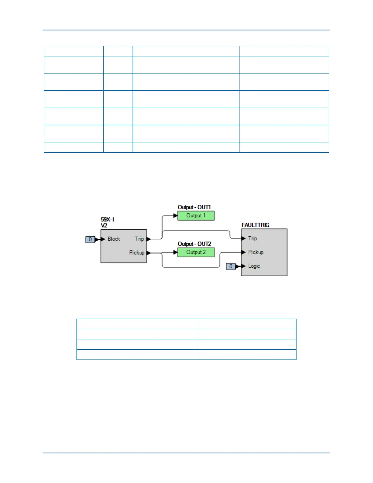
Step 2: Use BESTCOMSPlus to configure the BESTlogicPlus programmable logic shown in Figure 288.
• Blocking is disabled.
• OUT1 closes for 59X-1 Trip.
• OUT2 closes for 59X-1 Pickup.
• Fault recording is enabled.
Figure 288. BESTlogicPlus Settings (V2 Mode)
Step 3: Use BESTCOMSPlus to open the Protection, Voltage, Overvoltage (59X-1) screen and send
the first row of test settings in Table 164 to the BE1-11g.
Table 164. Pickup Test Settings (V2 Mode)
Step 4: Prepare to monitor the 59X-1 function operation. Operation can be verified by monitoring OUT2
(see Figure 288).
Step 5: Connect and apply a 240 Vac, single-phase voltage source to terminals C13 (A-phase) and C16
(neutral). For a single-phase input test, V2 = A-phase voltage / 3. Therefore, the BE1-11g
should pick up at a value of three times the setting value when applying only a single-phase
input. For example, to determine the pickup voltage value required for a BE1-11g with a pickup
setting of 82, it would require 82 times 3 or 246 volts of input voltage.
Step 6: Slowly increase the voltage until OUT1 closes and record the pickup. Verify that there is a 59X-
1-V2 target on the front-panel display. Slowly decrease the voltage until OUT1 opens and
record the dropout. Reset the target.
BE1-11g Auxiliary Overvoltage (59X) Test
 Loading...


