9424200994 Rev N 437
Table 183. Timing Test Settings (Phase Mode)
Step 5: Repeat step 4 for the 5,000 ms and 10,000 ms time delay settings of Table 183. Record the
results.
Step 6: (Optional.) Repeat steps 1 through 5 for the B-phase and C-phase current inputs.
Step 7: (Optional.) Repeat steps 1 through 6 for settings group 1, 2, and 3.
Step 8: (Optional.) Repeat steps 1 through 7 for 50-2, 50-3, 50-4, 50-5, and 50-6.
Step 9: (Optional.) Repeat steps 1 through 8 with CT Circuit 2 as the source for protection systems
equipped with two sets of CTs. In step 3, replace D1 with F1, D2 with F2, etc.
Pickup Verification (3I0 Mode)
Step 1: Use BESTCOMSPlus to send the operational settings in Table 184 to the BE1-11g. Reset all
targets.
Table 184. Operational Settings (3I0 Mode)
System Parameters, Sensing
Transformers
Protection, Current,
Instantaneous Overcurrent (50-1)
Enables 50-1 function for 3I0 mode
Protection, Current,
Instantaneous Overcurrent (50-1)
Selects CT circuit 1 as the source
Target Configuration, Targets
Enables residual target for 50-1
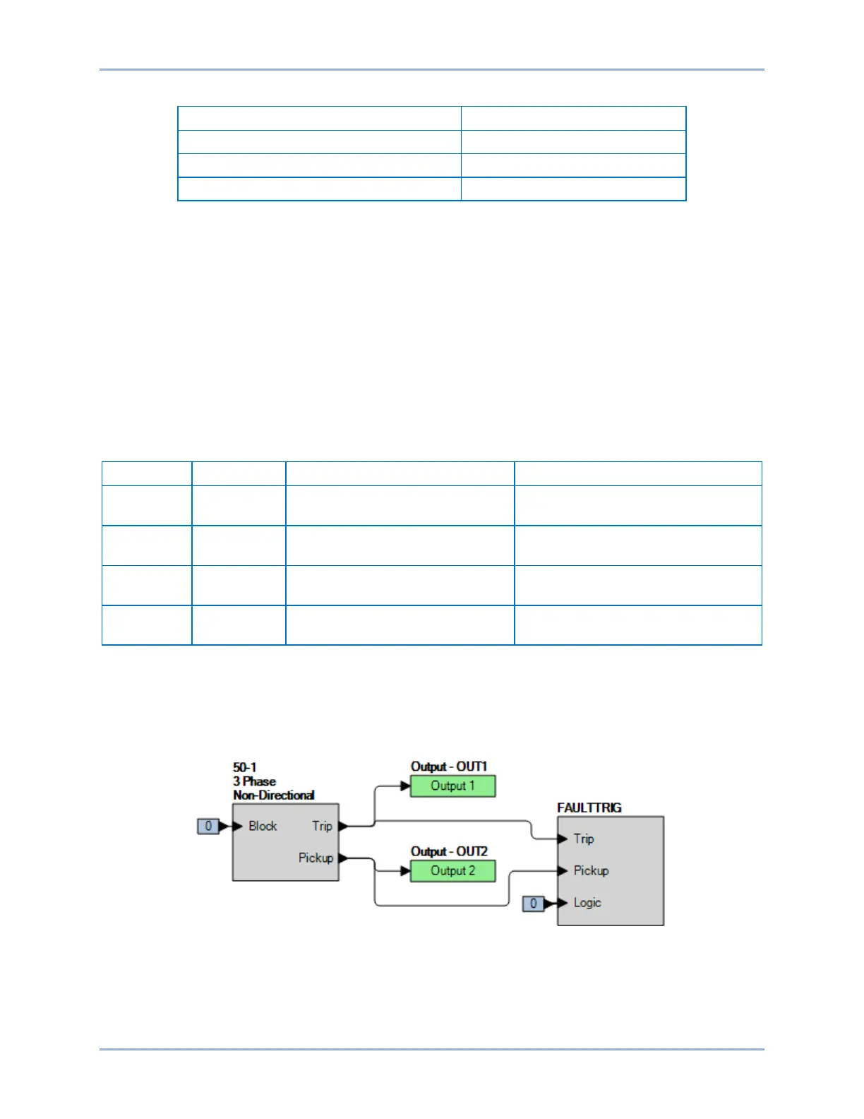
Step 2: Use BESTCOMSPlus to configure the BESTlogicPlus programmable logic shown in Figure 297.
• Blocking is disabled.
• OUT1 closes for 50-1 Trip.
• OUT2 closes for 50-1 Pickup.
• Fault recording is enabled.
Figure 297. BESTlogicPlus Settings (3I0 Mode)
Step 3: Use BESTCOMSPlus to open the Protection, Current, Instantaneous Overcurrent (50-1) screen
and send the low range test settings (minimum pickup setting) to the BE1-11g for your sensing
input type in Table 185.
BE1-11g Instantaneous Overcurrent (50) Test