9424200994 Rev N 517
Frequency Raise/Lower Continuous Output Verification
Step 1: Use BESTCOMSPlus to monitor the status of OUT2 (Lower) and OUT3 (Raise).
Step 2: Connect a balanced, three-phase voltage source of 69.28 Vpn, 60 Hz to BE1-11g terminals C13
(A-phase), C14 (B-phase), C15 (C-phase), and C16 (neutral). Apply a single-phase, 60-hertz
voltage of 69.28 Vpn, ∠0°, to terminals C17 (Vx-phase) and C18 (Vx-neutral). OUT2 and OUT3
should be open.
Step 3: Slowly increase the frequency of the phase voltage source until OUT2 closes continuously. This
should occur when the source is raised past the Min Slip setting (approximately 60.2 Hz).
Step 4: Decrease the frequency phase voltage source until OUT2 opens.
Step 5: Slowly decrease the frequency of the phase voltage source until OUT3 closes. This should
occur when the source is lowered past the Min Slip setting (approximately 59.8 Hz).
Step 6: (Optional.) Repeat steps 2 through 5 for settings group 1, 2, and 3.
Breaker Close Attempts/Sync Fail Activation Delay Verification
Step 1: Use BESTCOMSPlus to verify the settings in Table 235 to the BE1-11g and set the logic in
Figure 316.
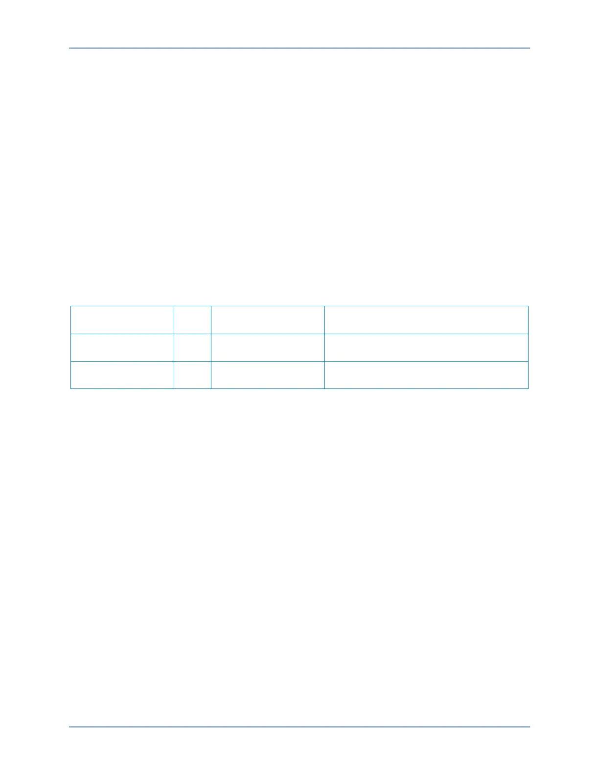
Table 235. Sync Fail Settings PLL (25A)
Setting Value
Description
Control, Synchronizer
(25A)
Sets the maximum number of allowable
breaker close attempts to 3
Sync Fail Activation
Delay (s)
Control, Synchronizer
(25A)
Sets the activation delay for the sync fail
alarm to 5 seconds
Step 2: Prepare to monitor the status of OUT1 (Close Breaker) and OUT8 (Sync Fail).
Step 3: Connect a balanced, three-phase voltage source of 69.28 Vpn, 60 Hz to BE1-11g terminals C13
(A-phase), C14 (B-phase), C15 (C-phase), and C16 (neutral). Apply a single-phase, 60-hertz
voltage of 69.28 Vpn, ∠0°, to terminals C17 (Vx-phase) and C18 (Vx-neutral). OUT1 and OUT8
should remain open.
Step 4: Apply contact sensing voltage to B3 (IN2+) and B4 (IN2-) to initiate a close attempt and cause
OUT1 to close. CAUTION: Applying voltage above the capabilities of the equipped power
supply could cause irreversible damage to the BE1-11g. Consult the Specifications chapter for
more information on contact input voltage ranges.
Step 5: OUT1 should make a total of three close attempts. OUT8 should close approximately 5 seconds
after the third close attempt.
Step 6: (Optional.) Repeat steps 2 through 5 for settings group 1, 2, and 3.
BE1-11g Synchronizer (25A) Test

 Loading...


