534 9424200994 Rev N
despite a second 43-1 OFF to ON initiate signal while the duration timer was active. Figure 324
illustrates the timing relationship of the 43-1 switch and 62-1 timer.
Figure 324. One-Shot/Non-Retriggerable Mode
Step 6: (Optional.) Repeat steps 1 through 5 for 62-1, 62-2, 62-3, 62-4, 62-5, 62-6, 62-7, and 62-8.
Step 7: (Optional.) Repeat steps 1 through 6 for settings group 1, 2, and 3.
One-Shot/Retriggerable Mode
Step 1: Use BESTCOMSPlus to send the operational settings in Table 243 to the BE1-11g. Retain the
logic settings from Figure 321.
Table 243. Operational Settings (One-Shot/Retriggerable Mode)
Control, Logic Timers (62)
Sets 62-1 to One-
Shot/Retriggerable mode
Control, Logic Timers (62)
Sets 62-1 pickup time delay to
15,000 ms
Control, Logic Timers (62)
Sets 62-1 dropout time delay
to 20,000 ms
Control, Virtual Control
Switches (43)
Target Configuration,
Targets screen.
Step 2: Step 4 supplies the 62-1 timer with a momentary initiate input by pulsing the 43-1 switch from
an OFF state to an ON state and then back to an OFF state. You can view the state changes of
the 43-1 switch at the Metering > Control > Virtual Switches screen on the front-panel display.
Step 3: Close communication with BESTCOMSPlus.
Step 4: Using the front-panel display, navigate to Metering > Control > Virtual Switches. Highlight the
first switch (43-1) and press the Right key on the front panel to enter the 43-1 control screen.
Use the Edit key to login. Highlight Operate and then press the Edit key to change the state of
the 43-1. Using the Up/Down keys select PUL and then press the Edit key.
Step 5: Repeat step 4.
Step 6: Wait at least 15 seconds (but no longer than 35 seconds) and then repeat step 4.
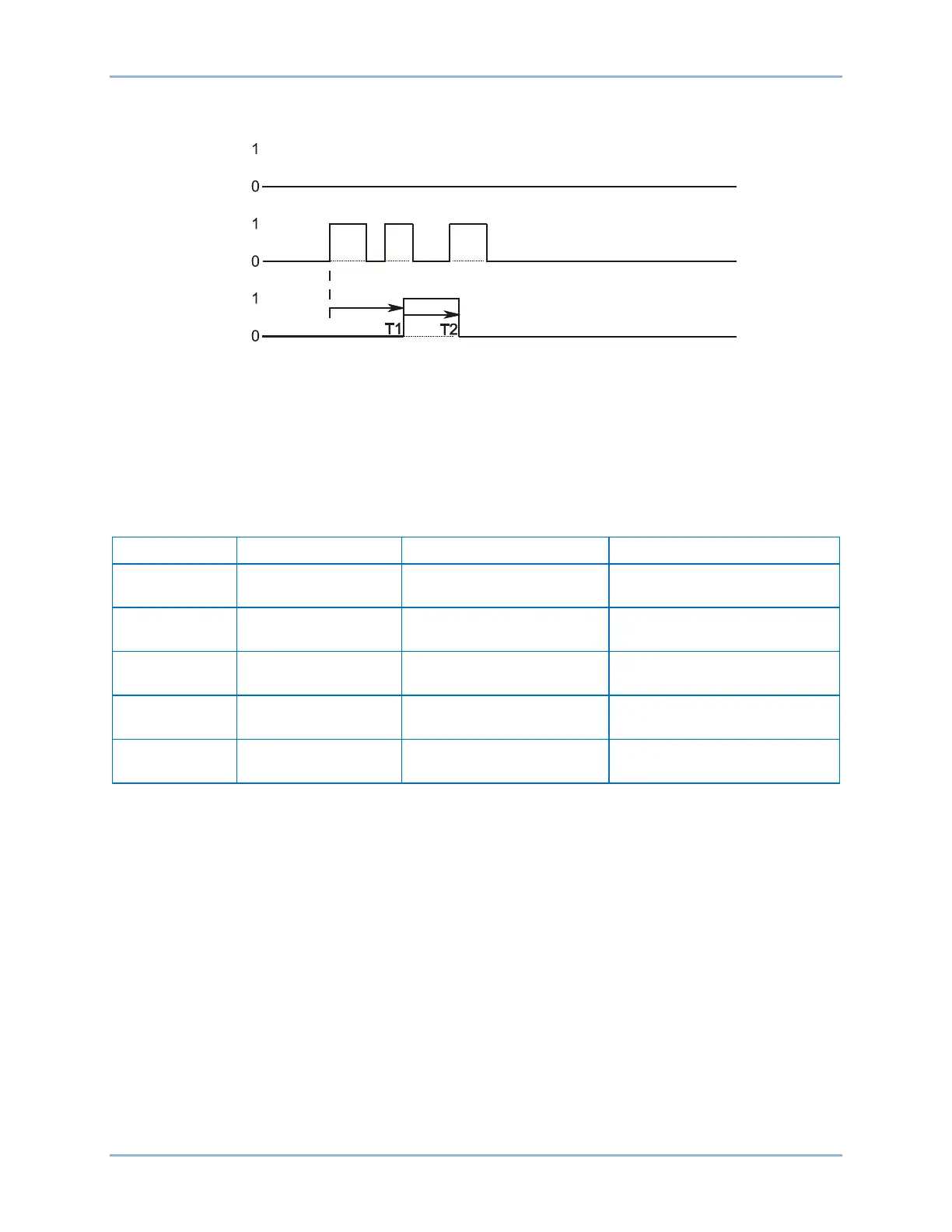
Step 7: Use the Metering Explorer in BESTCOMSPlus to open the Reports, Sequence of Events
screen. Verify that approximately 15 seconds after the second 43-1 OFF to ON initiate signal,
the 62-1 timer output went true. Verify that the timer output went false when the third OFF to ON
initiate signal forced the 62-1 time delay 1 to restart. Figure 325 illustrates the timing
relationship of the 43-1 switch and 62-1 timer.
P0035-31
02-27-06
Block
Initiate
62-x
Logic Timers (62) Test BE1-11g

 Loading...


