9424200994 Rev N 537
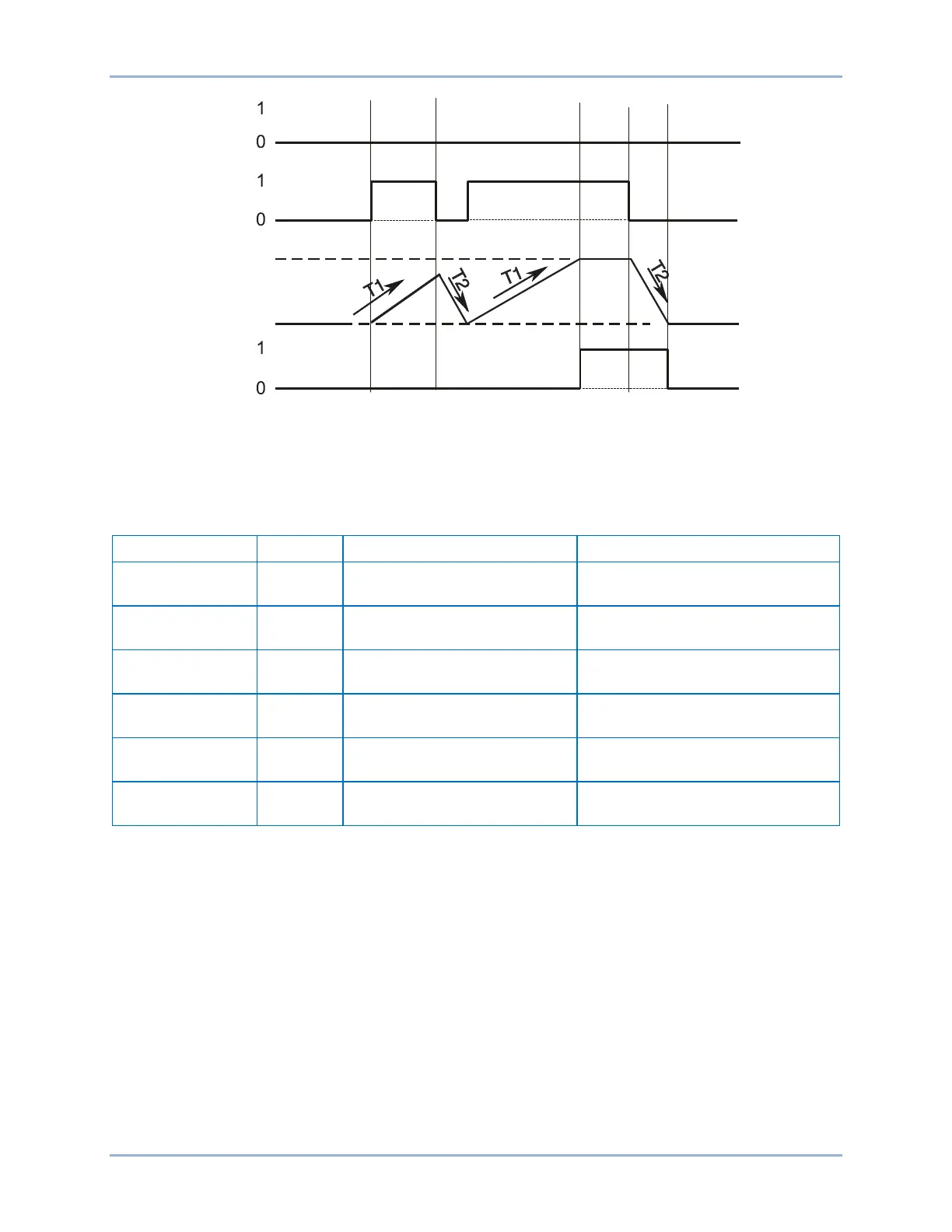
Figure 326. Integrating Timer Mode
Latched Mode
Step 1: Use BESTCOMSPlus to send the operational settings in Table 245 to the BE1-11g. Retain the
logic settings from Figure 321.
Table 245. Operational Settings (Latched Mode)
Control, Logic Timers (62)
Sets 62-1 to One-
Shot/Retriggerable mode
Control, Logic Timers (62)
Sets 62-1 pickup time delay to
15,000 ms
Control, Logic Timers (62)
Sets 62-1 dropout time delay to 0
Control, Virtual Control
Switches (43)
Control, Virtual Control
Switches (43)
Target Configuration, Targets
screen.
Step 2: Use BESTCOMSPlus to configure the BESTlogicPlus programmable logic shown in Figure 327.
• 62-1 initiates when 43-1 output is true.
• 62-1 is blocked when 43-2 output is true.
• OUT1 closes when 62-1 output is true.
Step 3: Step 5 supplies the 62-1 timer with a latch input by pulsing the 43-1 switch from an OFF state to
an ON state and then back to an OFF state. These commands also supply a block input when
the 43-2 is ON. You can view the state changes of the 43-1 switch at the Metering > Control >
Virtual Switches screen on the front-panel display.
Step 4: Close communication with BESTCOMSPlus.
P0035-34
02-27-06
62-x
Block
Initiate
100%
0%
Timer
BE1-11g Logic Timers (62) Test