4-44 DGC-2020 BESTCOMSPlus Software 9400200990 Rev I
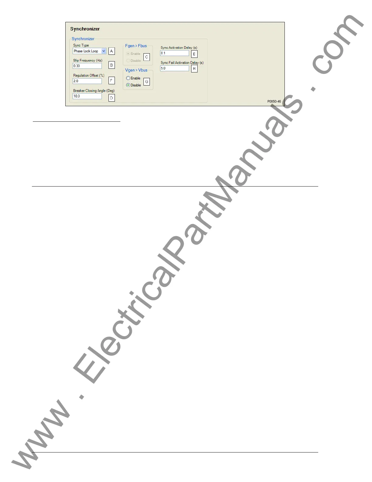
Figure 4-40. Synchronizer Settings
A
Sync Type: Phase Lock Loop or Anticipatory.
B
Slip Frequency: Adjustable from 0.05 to 0.5 Hz in 0.05 Hz increments.
C
Fgen>Fbus: Enable or Disable.
D
Breaker Closing Angle: Adjustable from 3 to 20° in 1 ° increments.
E
Sync Activation Delay: Adjustable from 0.1 to 0.8 seconds in 0.1s increments.
F
Regulation Offset: Adjustable from 2 to 15% of nominal generator voltage in 0.5% increments.
G
Vgen>Vbus: Enable or Disable.
H
Sync Fail Activation Delay: Adjustable from 0.1 to 600 in 0.1 s increments.
BIAS CONTROL SETTINGS
AVR Bias Control Settings
The bias control output type
A
should be set to contact when operating without an optional LSM-2020.
The DGC-2020 adjusts the generator voltage and frequency by issuing voltage correction signals to the
generator AVR (automatic voltage regulator). Correction signals are issued in the form of DGC-2020
output contact closures. These correction signals can be either continuous or proportional
B
. Proportional
correction uses control pulses of varying widths
C
and intervals
D
. Initially, long pulses are issued when the
voltage and frequency differences are large. As the correction pulses take effect and the voltage and
frequency differences become smaller, the correction pulse widths are proportionally decreased.
Proportional correction pulses are beneficial in applications where fixed correction pulses can result in
overshooting the slip frequency and regulation offset targets.
When an optional LSM-2020 is connected, the bias control output type
A
should be set to analog. This
enables a PID controller that controls the voltage bias from the LSM-2020 to the voltage regulator. The
controller adjusts the bias output to drive the error between desired generator voltage and measured
generator voltage to zero. Settings are provided for proportional gain
E
, integral gain
F
, derivative gain
G
,
derivative filter constant
H
, and loop gain
I
of the PID controller.
BESTCOMSPlus AVR bias control settings (DGC-2020, Bias Control Settings, AVR Bias Control
Settings) are illustrated in Figure 4-41.
www . ElectricalPartManuals . com