9400200990 Rev I DGC-2020 BESTCOMSPlus Software 4-45
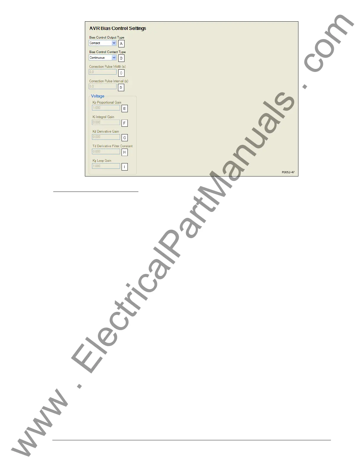
Figure 4-41. AVR Bias Control Settings
A
Bias Control Output Type: Contact or Analog.
B
Bias Control Contact Type: Continuous or Proportional.
C
Correction Pulse Width: Adjustable from 0 to 99.9 s in 0.1 s increments.
D
Correction Pulse Interval: Adjustable from 0 to 99.9 s in 0.1 s increments.
E
Proportional Gain (Kp): Adjustable from 0 to 1,000 in increments of 0.001.
F
Integral Gain (Ki): Adjustable from 0 to 1,000 in increments of 0.001.
G
Derivative Gain (Kd): Adjustable from 0 to 1,000 in increments of 0.001.
H
Derivative Filter Constant (Td): Adjustable from 0 to 1 in increments of 0.001.
I
Loop Gain (Kg): Adjustable from 0 to 1,000 in increments of 0.001.
Governor Bias Control Settings
The bias control output type
A
should be set to contact when operating without an optional LSM-2020.
The DGC-2020 adjusts the generator voltage and frequency by issuing speed correction signals to the
generator governor. Correction signals are issued in the form of DGC-2020 output contact closures.
These correction signals can be either continuous or proportional
B
. Proportional correction uses control
pulses of varying widths
C
and intervals
D
. Initially, long pulses are issued when the voltage and frequency
differences are large. As the correction pulses take effect and the voltage and frequency differences
become smaller, the correction pulse widths are proportionally decreased. Proportional correction pulses
are beneficial in applications where fixed correction pulses can result in overshooting the slip frequency
and regulation offset targets.
When an optional LSM-2020 is connected, the bias control output type
A
should be set to analog. This
enables a PID controller that controls the bias signal from the LSM-2020 to the speed governor. The
controller adjusts the bias output to drive the error between desired generator speed and measured
generator speed to zero. Settings are provided for proportional gain
E
, integral gain
F
, derivative gain
G
,
derivative filter constant
H
, and loop gain
I
of the PID controller.
The speed trim enable setting
J
sets speed trimming to rated speed when the generator breaker is closed
and the machine is not paralleled to the utility. If speed trimming is enabled in all generators in an
islanded system, it is ensured that the system will run at rated frequency. If it is not enabled in any units,
the islanded system may deviate from rated frequency, depending on the initial speed settings of the
isochronous governors.
BESTCOMSPlus governor bias control settings (DGC-2020, Bias Control Settings, Governor Bias Control
Settings) are illustrated in
Figure 4-42.
www . ElectricalPartManuals . com