9-6 DGC-2020 CEM-2020 (Contact Expansion Module) 9400200990 Rev I
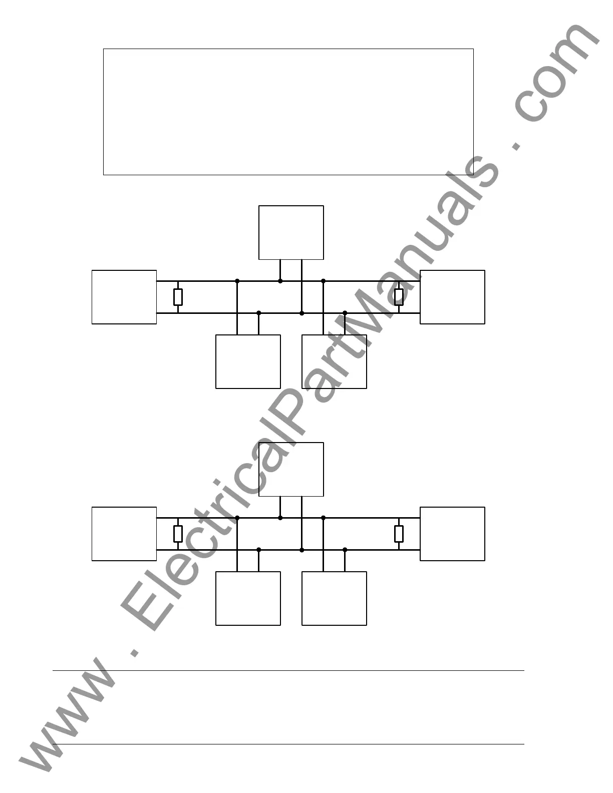
DGC-2020
CEM-2020
Other
Devices
P0053-09
Engine
120 ohm
Termination
120 ohm
Termination
CAN-H
CAN-L
LSM-2020
(Optional)
Figure 9-3. CANBus Interface with CEM-2020 providing One End of the Backbone
CEM-2020
DGC-2020
Other
Devices
P0053-10
Engine
120 ohm
Termination
120 ohm
Termination
CAN-H
CAN-L
LSM-2020
(Optional)
Figure 9-4. CANBus Interface with DGC-2020 providing One End of the Backbone
MAINTENANCE
Preventive maintenance consists of periodically checking that the connections between the CEM-2020
and the system are clean and tight. Contact Expansion Modules are manufactured using state-of-the-art
surface-mount technology. As such, Basler Electric recommends that no repair procedures be attempted
by anyone other than Basler Electric personnel.
NOTES
1.) If the CEM-2020 is providing one end of the J1939 backbone, a 120 Ω
terminating resistor should be installed across terminals P1 HI (CANH) and P1
LO (CANL).
2.) If the CEM-2020 is not part of the J1939 backbone, the stub connecting the
CEM-2020 to the backbone should not exceed 914 mm (3 ft) in length.
3.) The J1939 drain (shield) should be grounded at one point only. If grounded
elsewhere, do not connect the drain to the CEM-2020. The closest connection to
the center of the network should be used.
www . ElectricalPartManuals . com