5-16 DGC-2020 BESTlogic+ Programmable 9400200990 Rev I
Printing a BESTlogic+ File
To view a preview of the printout, click on the Print Preview icon located on the BESTlogic+
Programmable Logic toolbar. If you wish to print to a printer, select the printer icon in the upper left corner
of the Print Preview screen.
You may skip the print preview and go directly to print by clicking on the Printer icon on the BESTlogic+
Programmable Logic toolbar. A dialog box, Select Views to Print opens allowing you to check which views
you would like to print. Next, the Print dialog box opens with the typical Windows
®
choice to setup the
properties of printer. Execute this command, as necessary, and then select Print.
A Page Setup icon is also provided on the BESTlogic+ Programmable Logic toolbar allowing you to select
Paper Size, Paper Source, Orientation, and Margins.
Clearing the On-Screen Logic Diagram
Click on the Clear button to clear the on-screen logic diagram and start over.
BESTlogic+ EXAMPLES
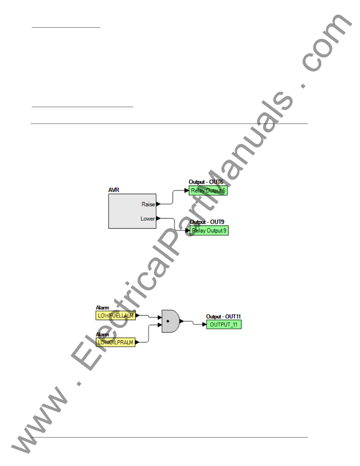
Example 1 - AVR Logic Block Connections
Figure 5-5 illustrates the AVR logic block and two output logic
blocks. Output 6 is active while the AVR is
being raised and Output 9 is active while the AVR is being lowered.
Figure 5-5. Example 1 - AVR Logic Block Connections
Example 2 - AND Gate Connections
Figure 5-6 illustrates a typical AND gate connection. In this example, Output 11 will becom
e active when
the Low Fuel alarm AND the Low Oil Pressure alarm are TRUE.
Figure 5-6. Example 2 - AND Gate Connections
Example 3 - Multiple Logic Connections
In this example, there are two comment boxes, which may be placed on the logic diagram. Double-click a
comment box to modify the inside text. Output 5 will become TRUE when the 27TRIP is TRUE. Output 7
will become TRUE when the Cool Temp Sender Fail is TRUE. Output 1 will become TRUE when the
DGC-2020 is in RUN mode (RUN Mode TRUE). Refer to Figure 5-7.
www . ElectricalPartManuals . com