5-2 DGC-2020 BESTlogic+ Programmable 9400200990 Rev I
BESTlogic+ Composition
There are three main groups of objects used for programming BESTlogic+. These groups are I/O,
Components, and Elements. For details on how these objects are used to program BESTlogic+, see the
paragraphs on Programming BESTlogic+.
I/O
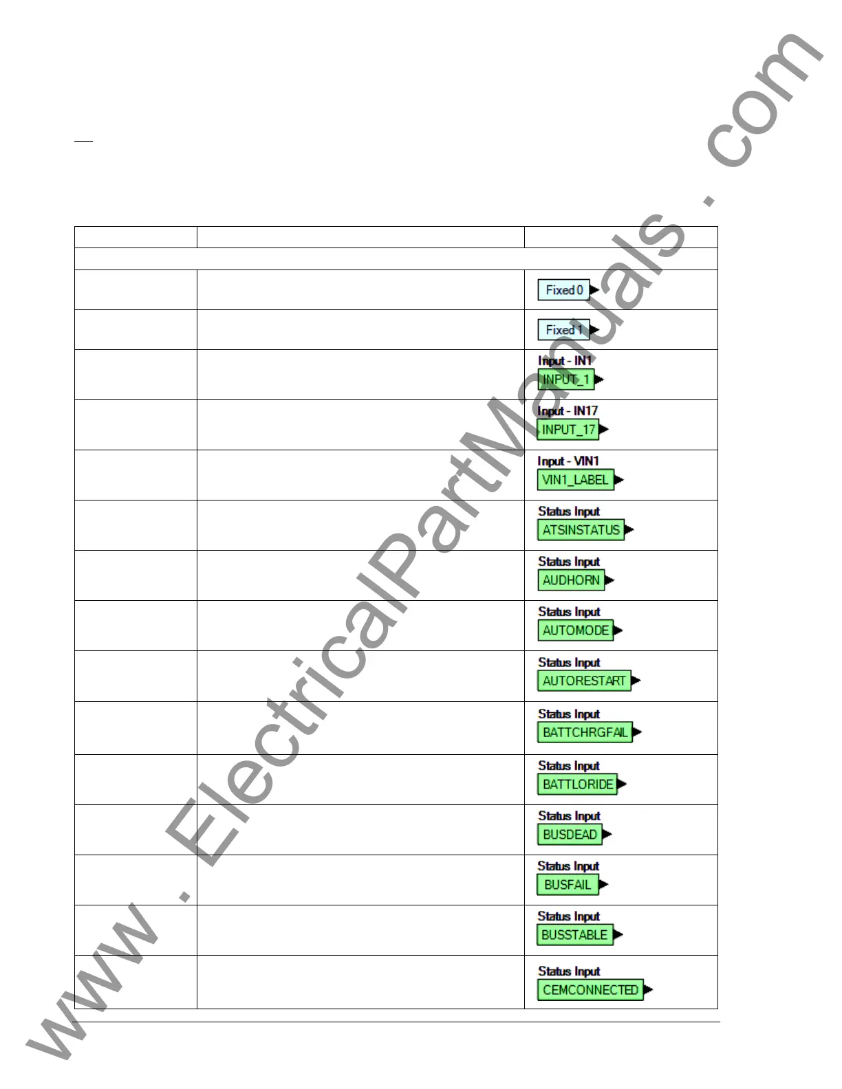
This group contains Input Objects, Output Objects, Alarms, Pre-Alarms, and Senders. Table 5-1 lists the
name
s and descriptions of the objects in the I/O group.
Table 5-1. I/O Group, Names and Descriptions
Name Description Symbol
Input Objects
Logic 0 Always FALSE (Low).
Logic 1 Always TRUE (High).
Physical Inputs
IN1 - IN16
TRUE when Physical Input x is active.
Remote Inputs
IN17 - IN26
True when Remote Input x is active.
(Available when an optional CEM-2020 is connected.)
Virtual Inputs
VIN1 - VIN4
TRUE when Virtual Input x is active.
Status Input
ATS Input
TRUE when the ATS (Auto Transfer Switch) input is
TRUE.
Status Input
Audible Horn
TRUE when the Audible Horn is active.
Status Input
Auto Mode
TRUE when the DGC-2020 is in Auto Mode.
Status Input
Auto Restart
TRUE when the Automatic Restart function is active.
Status Input
Battery Charger
Fail
TRUE when the Battery Charger Fail input is TRUE.
Status Input
Battle Override
TRUE when the Battle Override input is TRUE.
Status Input
Bus Dead
TRUE when the Bus Dead condition settings have been
exceeded.
Status Input
Bus Fail
TRUE when the Bus Fail condition settings have been
exceeded.
Status Input
Bus Stable
TRUE when the Bus Stable condition settings have been
exceeded.
Status Input
Contact Expansion
Module Connected
TRUE when an optional CEM-2020 is connected to the
DGC-2020.
www . ElectricalPartManuals . com