9400200990 Rev I DGC-2020 BESTlogic+ Programmable Logic 5-13
• Only ten gates per logic level. All output blocks and input sides of element blocks are at the maximum
logic level of the diagram. All gates are pushed forward/upwards in logic levels and buffered to reach
the final output block or element block if needed.
• At all levels there can only be 64 used link/wired or endpoints. Endpoints being inputs, outputs, both
sides of element blocks.
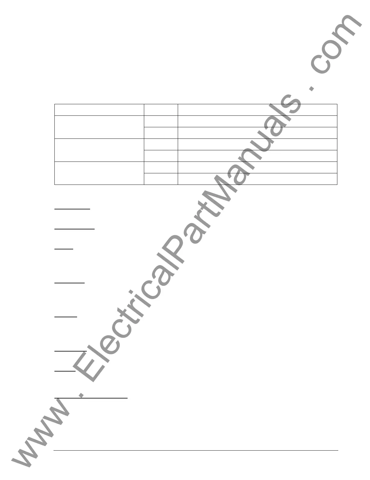
Three status LEDs are located in the lower right corner of the BESTlogic+ window. These LEDs show the
Logic Save Status, Logic Diagram Status, and Logic Layer Status.
Table 5-4 defines the colors for each
LED.
Table 5
-4. Status LEDs
LED Color Definition
Yellow Logic has changed since last save.
Logic Save Status
(Left LED)
Green Logic has NOT changed since last save.
Red Requirements NOT met as listed above.
Logic Diagram Status
(Center LED)
Green Requirements met as listed above.
Red Requirements NOT met as listed above.
Logic Layer Status
(Right LED)
Green Requirements met as listed above.
I/O
Input Objects
Input objects can be logically connected to any logic block input.
Output Objects
Output objects can be logically connected to any logic block output.
Alarms
There is a variety of alarms available in the DGC-2020. Use the drag and drop method to logically
connect an alarm to a logic input. More information on alarms is available in Section 3, Functional
Description.
Pre-Alarms
There is a variety of pre-alarms available in the DGC-2020. Use the drag and drop method to logically
connect a pre-alarm to a logic input. More information on pre-alarms is available in Section 3, Functional
Description.
Senders
Sender objects can be logically connected to any logic block input.
Components
Logic Gates
Logic gates available include AND, NAND, OR, NOR, XNOR, and NOT.
Latches
Latches are used to set and reset an output. Use the drag and drop method to logically connect the inputs
and output of the latch logic blocks.
Pickup and Dropout Timers
A pickup timer produces a TRUE output when the elapsed time is greater than or equal to the Pickup
Time setting after a FALSE to TRUE transition occurs on the Initiate input from the connected logic.
Whenever the Initiate input status transitions to FALSE, the output transitions to FALSE immediately.
A drop out timer produces a TRUE output when the elapsed time is greater than or equal to the Dropout
Time setting after a TRUE to FALSE transition occurs on the Initiate input from the connected logic.
Whenever the Initiate input transitions to TRUE, the output transitions to FALSE immediately.
www . ElectricalPartManuals . com