9400200990 Rev I DGC-2020 Time Overcurrent Characteristic Curves A-3
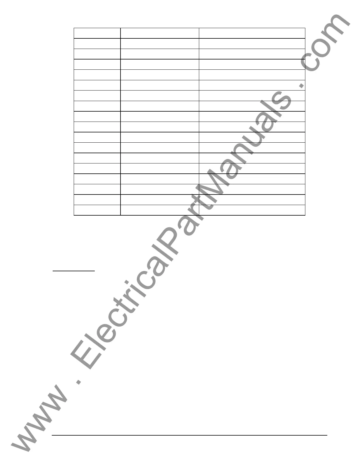
Table A-2. Characteristic Curve Cross-Reference
Curve Curve Name Similar To
S1
S, S1, Short Inverse ABB CO-2
S2
S2, Short Inverse GE IAC-55
L1
L, L1, Long Inverse ABB CO-5
L2
L2, Long Inverse GE IAC-66
D
D, Definite Time ABB CO-6
M
M, Moderately Inverse ABB CO-7
I1
I, I1, Inverse Time ABB CO-8
I2
I2, Inverse Time GE IAC-51
V1
V, V1, Very Inverse ABB CO-9
V2
V2, Very Inverse GE IAC-53
E1
E, E1, Extremely Inverse ABB CO-11
E2
E2, Extremely Inverse GE IAC-77
A
A, Standard Inverse BS, IEC Standard Inverse
B
B, Very Inverse (I
2
t) BS, IEC Very Inverse (I
2
t)
C
C, Extremely Inverse (I
2
t) BS, IEC Extremely Inverse (I
2
t)
G
G, Long Time Inverse (I
2
t) BS, IEC Long Time Inverse (I
2
t)
F
Fixed Time N/A
Time Dial Setting Cross-Reference
Although the time characteristic curve shapes have been optimized for the DGC-2020, the DGC-2020
time dial settings are not identical to the settings of electromechanical induction disk overcurrent relays.
Table A-3 helps you convert the time dial settings of induction disk relays to the equivalent setting for the
DGC-2020.
Using Table A-3
Cross-reference table values were obtained by inspection of published electromechanical time current
characteristic curves. The time delay for a current of five times tap was entered into the time dial
calculator function for each time dial setting. The equivalent DGC-2020 time dial setting was then entered
into the cross-reference table.
If your electromechanical relay time dial setting is between the values provided in the table, it will be
necessary to interpolate (estimate the correct intermediate value) between the electromechanical setting
and the Basler Electric setting.
The DGC-2020 has a maximum time dial setting of 9.9. The Basler Electric equivalent time dial setting for
the electromechanical maximum setting is provided in the cross-reference table even if it exceeds 9.9.
This allows interpolation as noted above.
Basler Electric time current characteristics are determined by a linear mathematical equation. The
induction disk of an electromechanical relay has a certain degree of non linearity due to inertial and
friction effects. For this reason, even though every effort has been made to provide characteristic curves
with minimum deviation from the published electromechanical curves, slight deviations can exist between
them.
In applications where the time coordination between curves is extremely close, we recommend that you
choose the optimal time dial setting by inspection of the coordination study. In applications where
coordination is tight, it is recommended that you retrofit your circuits with Basler Electric electronic relays
to ensure high timing accuracy.
www . ElectricalPartManuals . com