9400200990 Rev I DGC-2020 Modbus™ Communication B-15
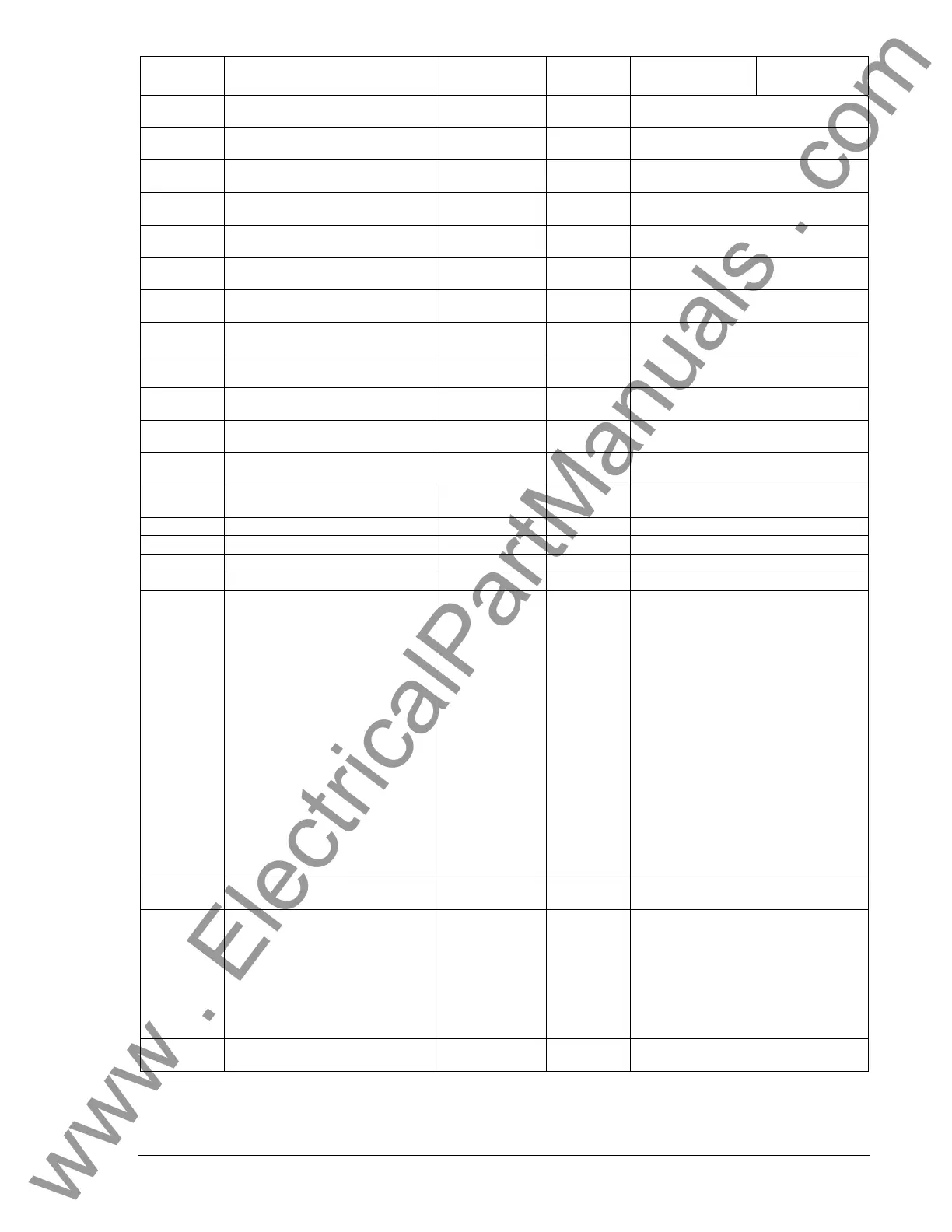
Holding
Register
Parameter Range
Read/Write
Supported
Data
Format
Units
40351
Previous DTC Number 10 – Upper
Two Bytes
0-65535 R
Half of a set of DTC data as defined in
SAE J1939-73
40352
Previous DTC Number 11 – Lower
Two Bytes
0-65535 R
Half of a set of DTC data as defined in
SAE J1939-73
40353
Previous DTC Number 11 – Upper
Two Bytes
0-65535 R
Half of a set of DTC data as defined in
SAE J1939-73
40354
Previous DTC Number 12 – Lower
Two Bytes
0-65535 R
Half of a set of DTC data as defined in
SAE J1939-73
40355
Previous DTC Number 12 – Upper
Two Bytes
0-65535 R
Half of a set of DTC data as defined in
SAE J1939-73
40356
Previous DTC Number 13 – Lower
Two Bytes
0-65535 R
Half of a set of DTC data as defined in
SAE J1939-73
40357
Previous DTC Number 13 – Upper
Two Bytes
0-65535 R
Half of a set of DTC data as defined in
SAE J1939-73
40358
Previous DTC Number 14 – Lower
Two Bytes
0-65535 R
Half of a set of DTC data as defined in
SAE J1939-73
40359
Previous DTC Number 14 – Upper
Two Bytes
0-65535 R
Half of a set of DTC data as defined in
SAE J1939-73
40360
Previous DTC Number 15 – Lower
Two Bytes
0-65535 R
Half of a set of DTC data as defined in
SAE J1939-73
40361
Previous DTC Number 15 – Upper
Two Bytes
0-65535 R
Half of a set of DTC data as defined in
SAE J1939-73
40362
Previous DTC Number 16 – Lower
Two Bytes
0-65535 R
Half of a set of DTC data as defined in
SAE J1939-73
40363
Previous DTC Number 16 – Upper
Two Bytes
0-65535 R
Half of a set of DTC data as defined in
SAE J1939-73
40364 RESERVED
40365 RESERVED
40366 RESERVED
40367 RESERVED
40368
DTC Lamp Status
NOTE: Even bits are Always a
Zero Value.
individual bits
are 0 or 1
R
Active stored in upper byte – Previous
stored in lower byte.
b0 = 0,
b1 = Protect Lamp,
b2 = 0,
b3 = Amber Warning Lamp,
b4 = 0,
b5 = Red Stop Lamp,
b6 = 0,
b7 = Malfunction Indicator Lamp,
b8 = 0,
b9 = Protect Lamp,
b10 = 0,
b11 = Amber Warning Lamp,
b12 = 0,
b13 = Red Stop Lamp,
b14 = 0,
b15 = Malfunction Indicator Lamp
40369 Number of DTC’s 0-65535 R
Active stored in upper byte – Previous
stored in lower byte.
40370 CAN Bus Results Register
individual bits
are 0 or 1
R
b0 = CAN Comms. Fail,
b1 = Active DTC Clear Fail,
b2 = Previous DTC Clear Fail,
b3 = DTC Values Changed,
b4 = CAN Hardware Test Pass,
b5 = UNASSIGNED,
b6 = UNASSIGNED,
b7 = UNASSIGNED,
40371
CAN Related Parameter: Percent
Coolant Level
0-100 R Percent
www . ElectricalPartManuals . com