9400200990 Rev I DGC-2020 Modbus™ Communication B-19
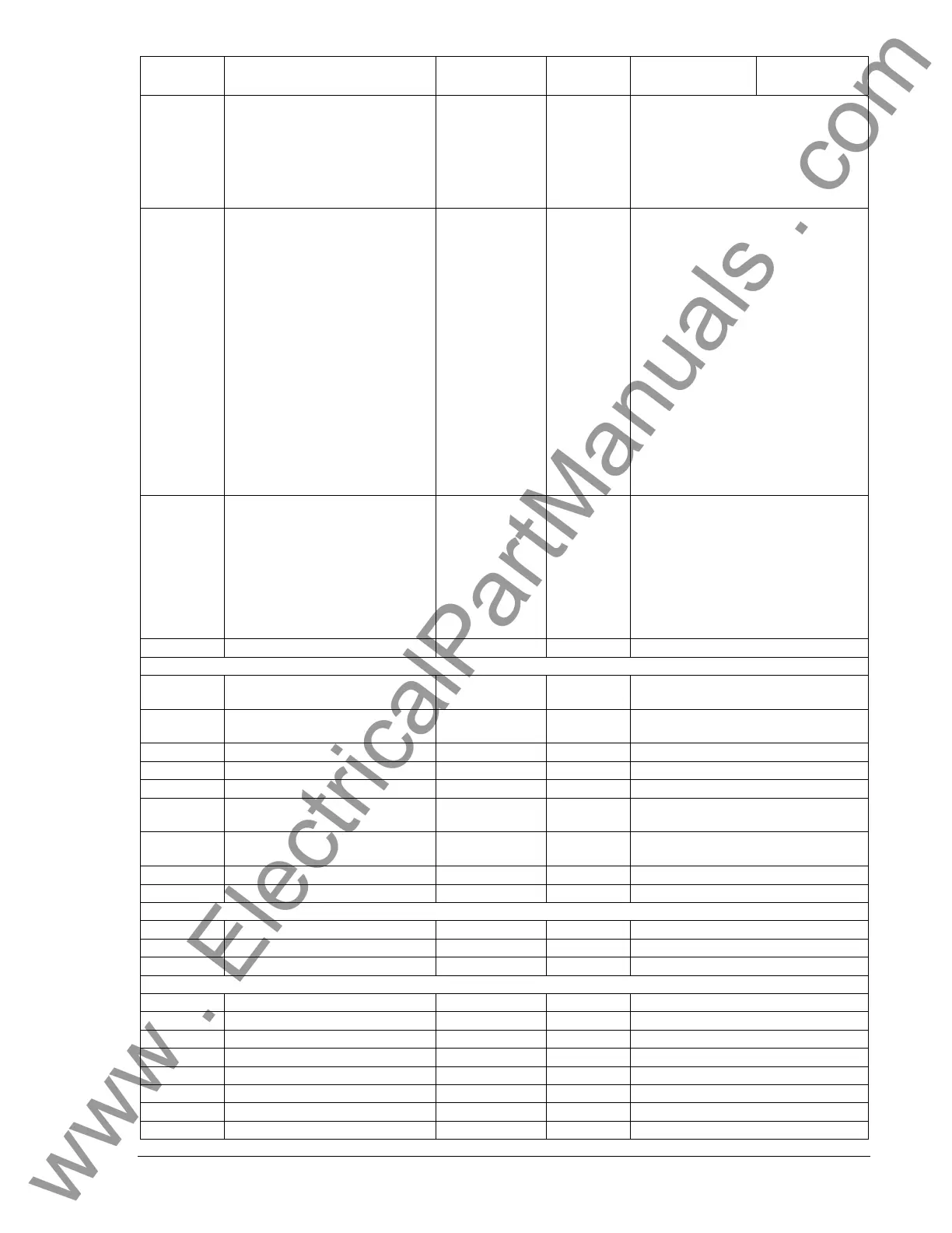
Holding
Register
Parameter Range
Read/Write
Supported
Data
Format
Units
40504 LED Status
individual bits
are 0 or 1
R
Bits indicate status of LED’s:
b0 = RUN
b1 = OFF
b2 = AUTO
b3 = ALARM
b4 = LOAD
b5 = NOT IN AUTO
40507
Read Relay Image of both Main
and Aux Output
(Duplicate of 40298)
individual bits
are 0 or 1
R
Main is in lower byte and Aux is in
upper byte.
b0 = Aux Output 1,
b1 = Aux Output 2,
b2 = Aux Output 3,
b3 = Aux Output 4,
b4 = Aux Output 5,
b5 = Aux Output 6,
b6 = Aux Output 7,
b7 = Aux Output 8.
b8 = Master Start Relay,
b9 = Fuel Solenoid Relay,
b10 = PreHeat PreLube Relay,
b11 = Alarm Relay,
b12 = UNASSIGNED,
b13 = Buzzer On,
b14 = EPS Loaded Relay,
b15 = PreAlarm Relay,
40508
Input Contacts States
(Duplicate of 40273)
individual bits
are 0 or 1
R
b0 = coolant level,
b1 = ATS,
b2 = E-stop,
b3 = charger failed,
b4 = aux. input 1,
b5 = aux. input 2,
b6 = aux. input 3,
b7 = aux. input 4. /* b7 =
aux. input 4. */
40509-604 RESERVED
OVERCURRENT
40605 51 Pick-up – 3-phase
18-118,
90-775
R W
0.18-1.18 Aac for 1A CTs,
0.90-7.75 Aac for 5A CTs
40606 51 Time Dial – 3-phase
0-99,
0-300
R W
0.0-9.9 for 40607=0-15 (inverse),
0.0-30.0s for 40607=16 (fixed)
40607 51 Curve – 3-phase 0-16 R W 0-15 for inverse, 16 for fixed
40608 51 Alarm Config. – 3-phase 0-2 R W 0=None, 1=Pre-Alarm, 2=Alarm
40609 51 Pick-up – 1-phase
18-118,
90-775
R W
0.18-1.18 Aac for 1A CTs,
0.90-7.75 Aac for 5A CTs
40610 51 Time Dial – 1-phase
0-99,
0-300
R W
0.0-9.9 for 40607=0-15 (inverse),
0.0-30.0s for 40607=16 (fixed)
40611 51 Curve – 1-phase 0-16 R W 0-15 for inverse, 16 for fixed
40612 51 Alarm Config. – 1-phase 0-2 R W 0=None, 1=Pre-Alarm, 2=Alarm
PHASE IMBALANCE
40613 47 Pick-up 5-100 R W Volts AC
40614 47 Time Delay 0-300 R W 0.0-30.0 seconds
40615 47 Alarm Configuration 0-2 R W 0=None, 1=Pre-Alarm, 2=Alarm
UNDERVOLTAGE
40616 27 Pick-up – 3-phase 70-576 R W Volts AC
40617 27 Time Delay – 3-phase 0-300 R W 0.0-30.0 seconds
40618 27 Inhibit Frequency- 3-ph. 20-400 R W Hertz
40619 27 Alarm Config. – 3-phase 0-2 R W 0=None, 1=Pre-Alarm, 2=Alarm
40620 27 Pick-up – 1-phase 70-576 R W Volts AC
40621 27 Time Delay – 1-phase 0-300 R W 0.0-30.0 seconds
40622 27 Inhibit Frequency – 1-ph. 20-400 R W Hertz
40623 27 Alarm Config. – 1-phase 0-2 R W 0=None, 1=Pre-Alarm, 2=Alarm
www . ElectricalPartManuals . com