Operation and Features
BASLER L304
kc 3-21
Draft
3.5.6 System Design Calculations
Assuming that the camera operating requirements listed in Section 3.5.4 and the system design
requirements listed in Section 3.5.5 are met, the formulas below can be used to calculate the basic
design criteria for your system.
Magnification
where: β = magnification
n = number of line captures needed to move the image from sensor line
to sensor line (see Table 3-3)
∆y = distance the conveyor moves per line capture
Line of View
where: L = length of the line of view of each sensor line
Aspect Ratio
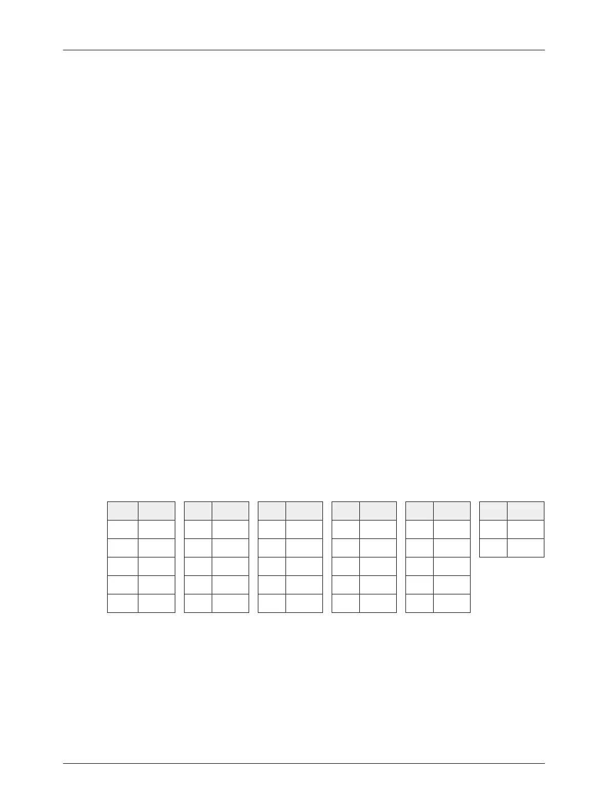
The aspect ratio of your captured images is determined by the value of “n” in the magnification
equation. The value can be set from 1 to 27. If the value is set to 9, the aspect ratio of the captured
images will be 1 to 1. The aspect ratios for various values of “n” are listed in Table 3-3. The aspect
ratios in the table are width to height where width is in the direction of conveyor travel and height
is along the axis of the sensor lines.
Once the magnification has been determined, you can select a lens with the appropriate focal
length and determine the correct distance between the camera and the conveyor. A publication
called the Optics Recommendation Guide is available on the Basler web site
(www.baslerweb.com/produkte/produkte_en_230.php). This publication provides general
guidance for selecting a lens. If you need more assistance with your lens selection, please contact
Basler Technical Support.
n Ratio n Ratio n Ratio n Ratio n Ratio n Ratio
1
1/9 6 2/3 11 11/9 16 16/9 21 7/3 26 26/9
2
2/9 7 7/9 12 4/3 17 17/9 22 22/9 27 3/1
3
1/3 8 8/9 13 13/9 18 2/1 23 23/9
4 4/9 9 1/1 14 14/9 19 19/9 24 8/3
5 5/9 10 10/9 15 5/3 20 20/9 25 25/9
Table 3-3: Aspect Ratios for Values of n
β
90 µm
n
∆× y
----------------
=
L 40.80 mm
1
β
---
×=
 Loading...


