Camera Interface
2-2 BASLER L304kc
Draft
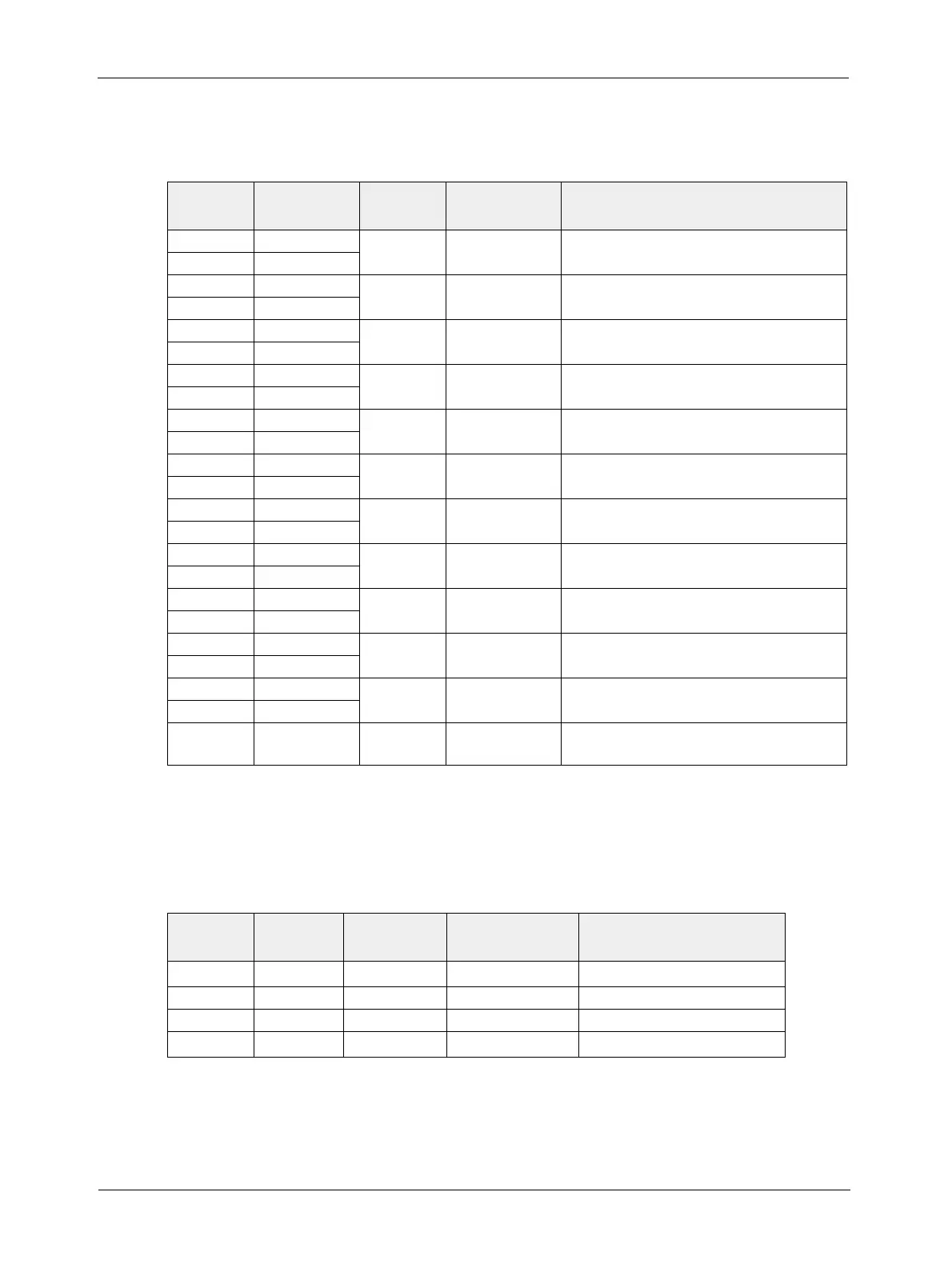
2.1.2 Pin Assignments and Pin Numbering
26-Pin MDR Connector Pin Assignments
6-Pin Micro-miniature Receptacle Pin Assignments
Pin
Number
Signal
Name
Direction Level Function
15 Tx X0+ Output Camera Link
LVDS
Data from Camera Link Transmitter
2Tx X0-
16 Tx X1+
Output Camera Link
LVDS
Data from Camera Link Transmitter
3Tx X1-
17 Tx X2+
Output Camera Link
LVDS
Data from Camera Link Transmitter
4Tx X2-
19 Tx X3+
Output Camera Link
LVDS
Data from Camera Link Transmitter
6Tx X3-
18
Tx Clk+ Output Camera Link
LVDS
Transmit Clock from Camera Link Transmitter
5
Tx Clk-
12
CC4+ Not Connected
25
CC4-
24 CC3+ Output RS-644
LVDS
Integrate Enabled
11
CC3-
10 CC2+ Input RS-644
LVDS
Not Used
23
CC2-
22 CC1+ Input RS-644
LVDS
External Trigger (ExSync)
9
CC1-
21 SerTFG+ Output RS-644
LVDS
Serial Communication Data Transmit
8
SerTFG-
7 SerTC+ Input RS-644
LVDS
Serial Communication Data Receive
20
SerTC-
1, 13,
14, 26
1
DC Gnd
Input Ground DC Ground
1
Pins 1, 13, 14 and 26 are all tied together inside of the camera.
Table 2-1: Pin Assignments for the 26-pin MDR Connector
Pin
Number
Signal
Name
Direction Level Function
1, 2
1
12 V In Input +12 VDC Camera Power Input
3
Not Connected
4
Not Connected
5, 6
2
DC Gnd
Input Ground DC Ground
1
Pins 1 and 2 are tied together inside of the camera.
2
Pins 5 and 6 are tied together inside of the camera.
Table 2-2: Pin Assignments for the 6-pin Micro-miniature Receptacle
 Loading...


