Camera Interface
BASLER L304
kc 2-1
Draft
2 Camera Interface
2.1 Connections
2.1.1 General Description
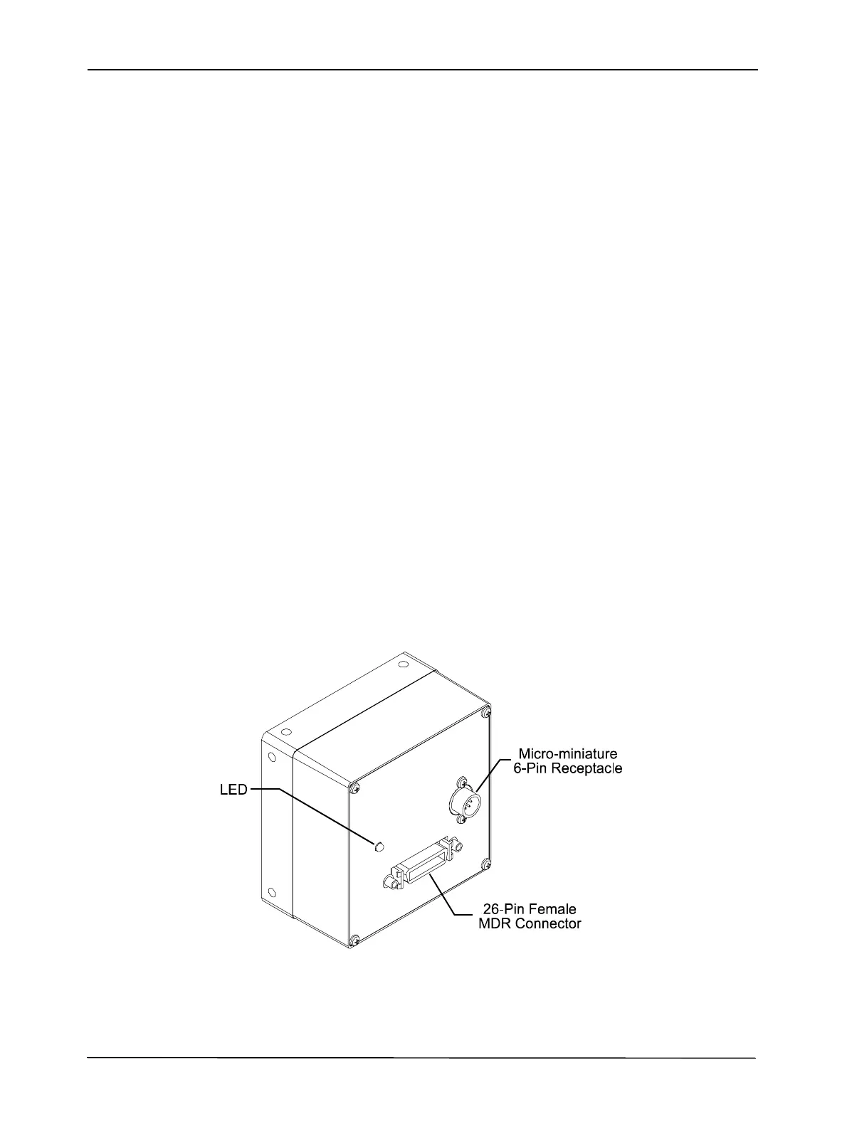
L304kc cameras are interfaced to external circuitry via two connectors located on the back of the
camera:
• a 26-pin, 0.050 inch Mini D Ribbon (MDR) female connector used to transmit video data,
control data and configuration data.
• a 6-pin, micro-miniature, push-pull receptacle used to provide power to the camera.
A status LED located on the back of the camera is used to indicate power present and to display
the camera’s status. Figure 2-1 shows the connectors and the LED.
Figure 2-1: Connectors and LED
 Loading...


