Installation
Instruction handbook b maXX BM5500, BM5600, BM5700
Document No.: 5.13008.10
201
of 314
7
Add-on module SIE
SSI encoder emulation, 2 channels, BM5XXX-XXXX-XX03
Set values for SSI encoder emulation can be evaluated from following sources:
m Position actual values encoder 1 or encoder 2
m Position set values (e. g. internal from positioning)
m Fieldbus set value (external set via bus)
The generated signal can be used either for synchronization of the following axis or for
position evaluation of the axis by the master control.
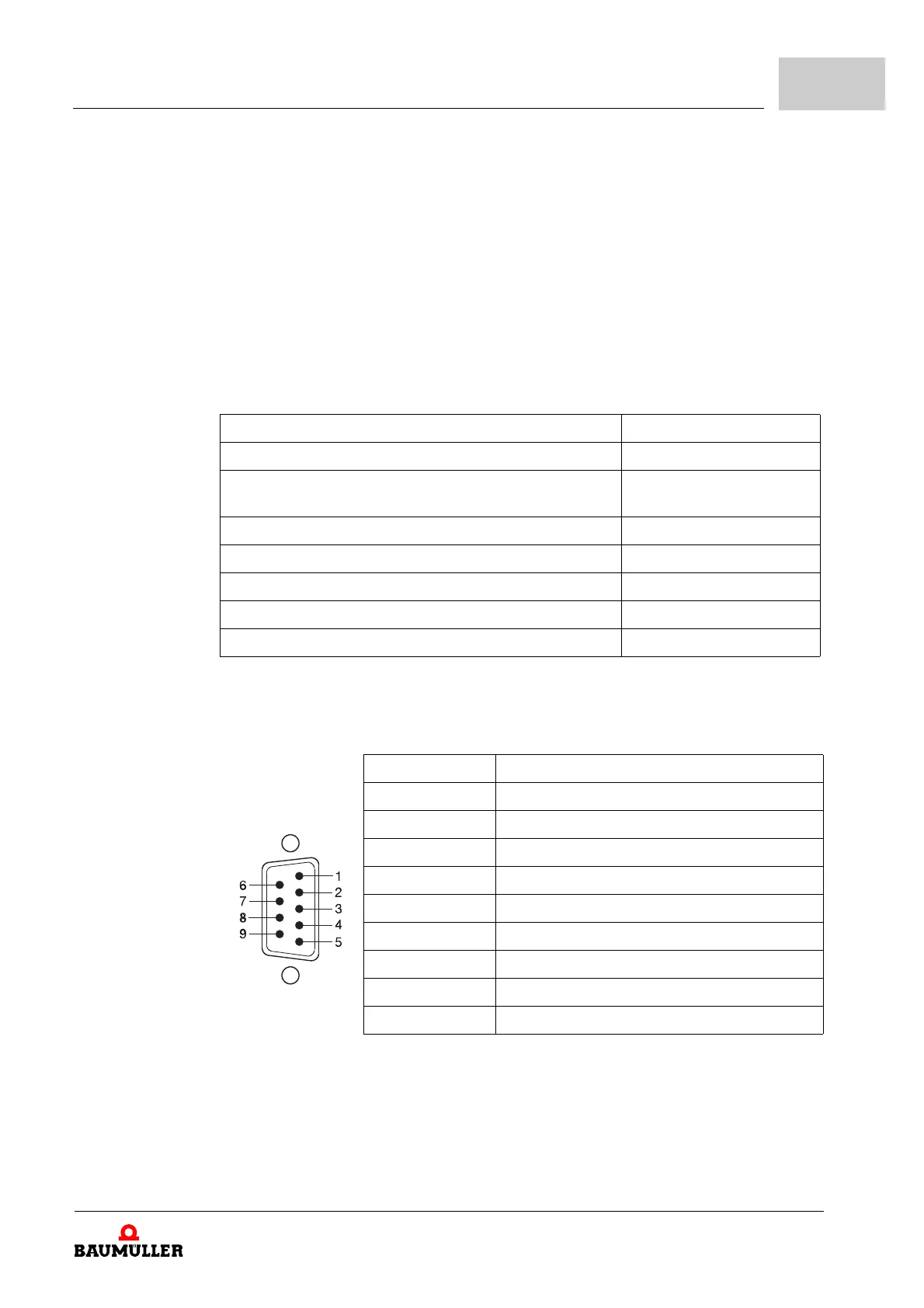
Pin assignment Sub-D on front side X1 and X2 (male) of SSI encoder emulation:
Connection cable refer to ZConnection cable add-on modules– on page 264.
Further information refer to manual add-on modules IEE/SIE, 5.13030.
Signal level: output high voltage at I
0H
= -20 mA 2.5 V
Signal level: output high voltage at I
0L
= +20 mA 0.5 V
Output frequency track signals Min. 200 kHz
Max. 1 MHz
Switching time: rise time < 50 ns
Switching time: fall time < 50 ns
Delay time It
d
I = 1 b 50 ns
Power input 0.525 W
Current output driver Max. 15 mA
Pin assignment Pin No. SSI assignment
Sub-D male connector
9-pole
1 Ground incremental encoder emulation
2 Not assigned
3 Not assigned
4 Not assigned
5 DAT +
6 Not assigned
7 CLK +
8 CLK +
9 DAT +