* is only valid for BM444X, BM464X, BM445X, BM465X, BM446X, BM466X accordingly the
cooling versions S and A, for BM447X cooling version -A:
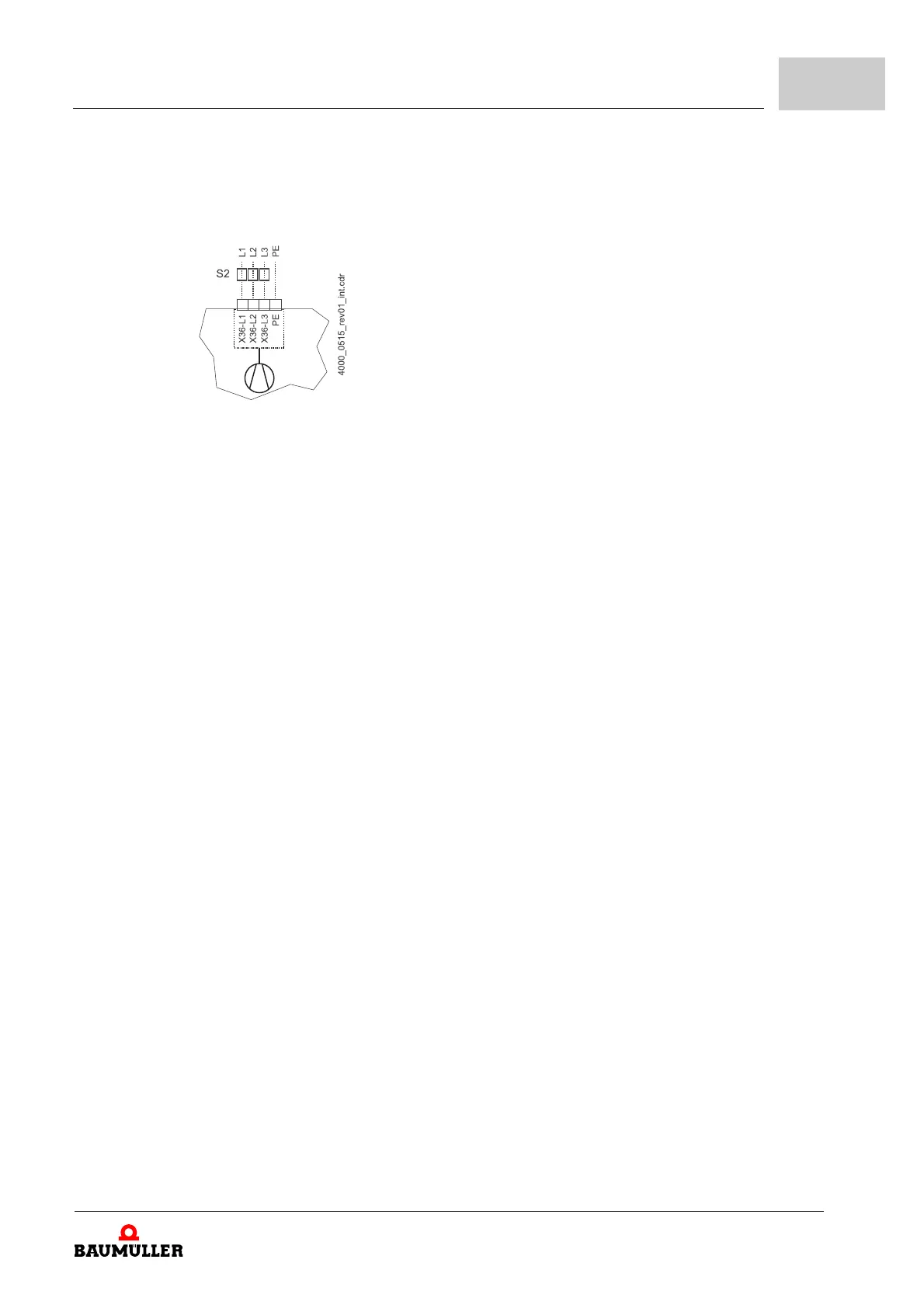
Figure 81: Connection fan
** The power supply at X100 or X101 must externally be protected. At selection of the fuse
you must consider the cross-section of the connecting cable and the maximum allowable
load capacity (for X100: see X100 on ZPag
e 193–, for X101: see X101 on ZPage 194–).
In case you consider UL 508 C, you
must limit the power supply to 100 W or fuse it with a
UL-listed 4 A fuse.
Ba- ... 1D1 Connections for brake resistor and DC link, see ZFig
ure 82– on page 181 and the follow-
ing
R
B
Brake resistor
PE....1W1 Power supply connection, see ZF
igure 82– on page 181 and the following
S1 Fuse (cable + device), see ZFu
ses– from page 273
S2 Fuse (fan) *)
S3 Fuses brake resistor circuit (required for BM447X, BM477X),
see ZFuses BM447X– on
page 292.
S4 DC link fuse
L1 Power choke (not necessary for BM441X and BM442X except BM4426)
L2 Mains filter
X1 Serial interface (RS 232), see ZF
igure 91– on page 196.
X3 Connections for ready-for-use, quick stop, pulse enable, see ZFig
ure 91– on page 196.
X36 Connections for fans (only BM444X-S/-A, BM445X-S/-A, BM465X
-S/-A, BM446X-S/-A,
BM466X-S/-A, BM447X-A)
X100 Connections for 24 V power supply, additional data see ZFigu
re 91– on page 196 (SELV/
PELV) and table ZX100 (SELV/PELV)– o
n page 193.
X101 Terminals for brake, motor temperature, see ZFig
ure 82– on page 181 and the following
(SELV/PELV) and table X101 from ZPage
181–.
Installation
Instruction handbook b maXX BM4400, BM4600, BM4700
Document No.: 5.12008.07
179
of 358
7