07-19-B1-729 FLO-GARD 6301 DUAL CHANNEL VOLUMETRIC INFUSION PUMP SERVICE MANUAL 9-3
Calibration DC Line Voltage Calibration
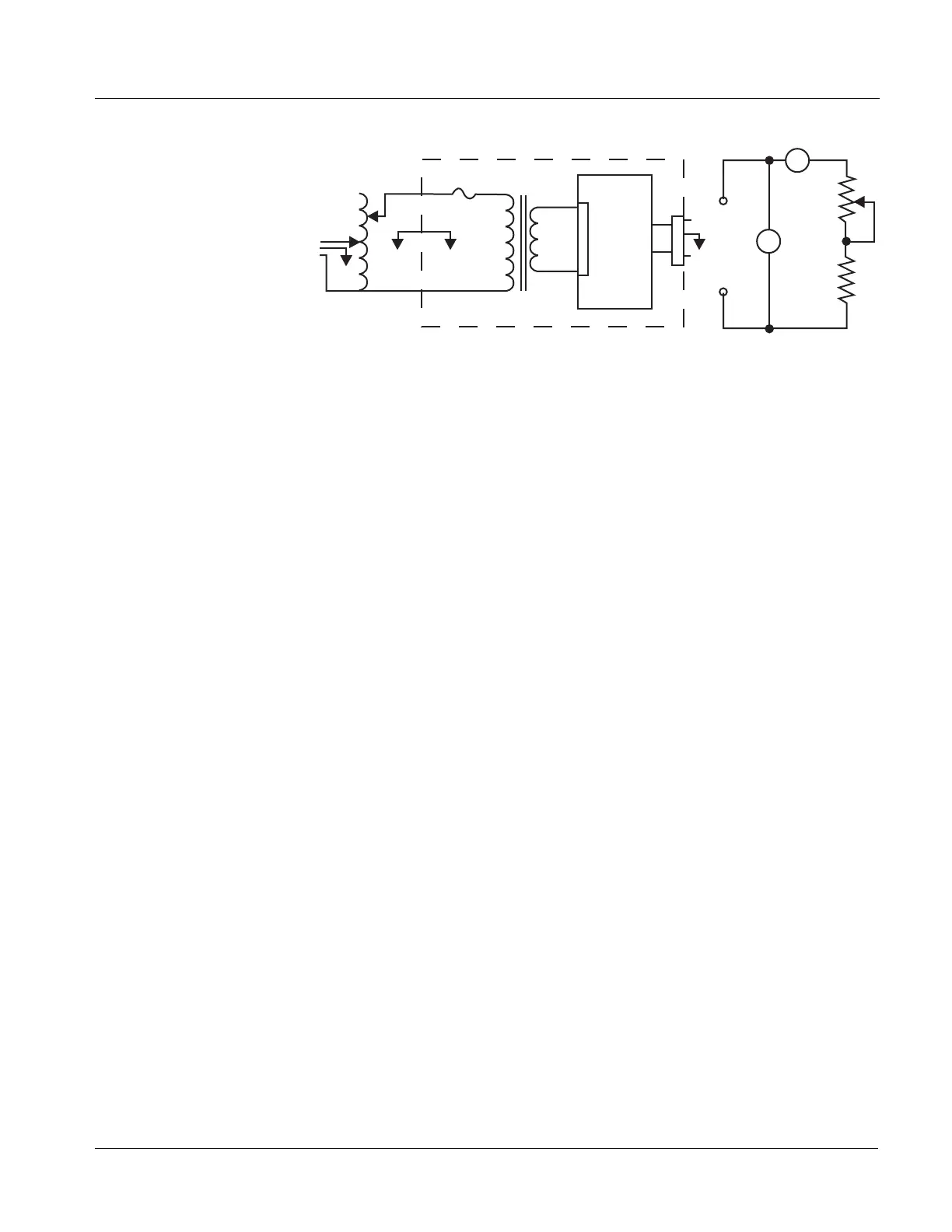
Figure 9-1 Calibration Equipment Setup
14.2 Separate the front and rear housings completely in accordance
with “Separation of Front and Rear Housings” on page 8-5.
14.3 Disconnect the power supply connector (CN301) from the CPU
board (Figure 11-2 , item 2) and connect it to the resistive load.
14.4 Connect the resistive load as illustrated in Figure 9-1 with the
positive lead connected to pin 2 and the negative lead
connected to pin 3.
14.5 Plug all calibration equipment into a 115 ± 5.0 VAC, 60 Hz
power source. Set as follows:
• Variable transformer: 0 V or minimum setting.
• Minimum current setting: constant current mode.
14.6 Turn potentiometers VR1 and VR2 on the DC power supply
board (Figure 11-3 , item 17) fully clockwise.
14.7 Set the DC ammeter to the appropriate range and the DC
voltmeter to 20 VDC range. Do not use autorange.
Calibration of Output Current Limit by VR2
14.8 Ensure the AC power plug of the pump is connected to the
variable transformer.
14.9 Adjust the variable transformer output to 120 VAC. The
voltage may be checked with an ordinary tester with ±3%
accuracy.
14.10 Adjust the potentiometer until the output current is 1.40 A.
Variable
Transformer
0.5 A SB
AC In
Power
Transformer
DC Power Supply
Board
CN301
Pump
Resistive Load
5 Ohm
20 W
5 Ohm
20 W
A
V
1
2
3
+
-
+-



 To Next Page