07-19-B1-729 FLO-GARD 6301 DUAL CHANNEL VOLUMETRIC INFUSION PUMP SERVICE MANUAL 8-21
Removal/Replacement Procedures Disassembly/Reassembly
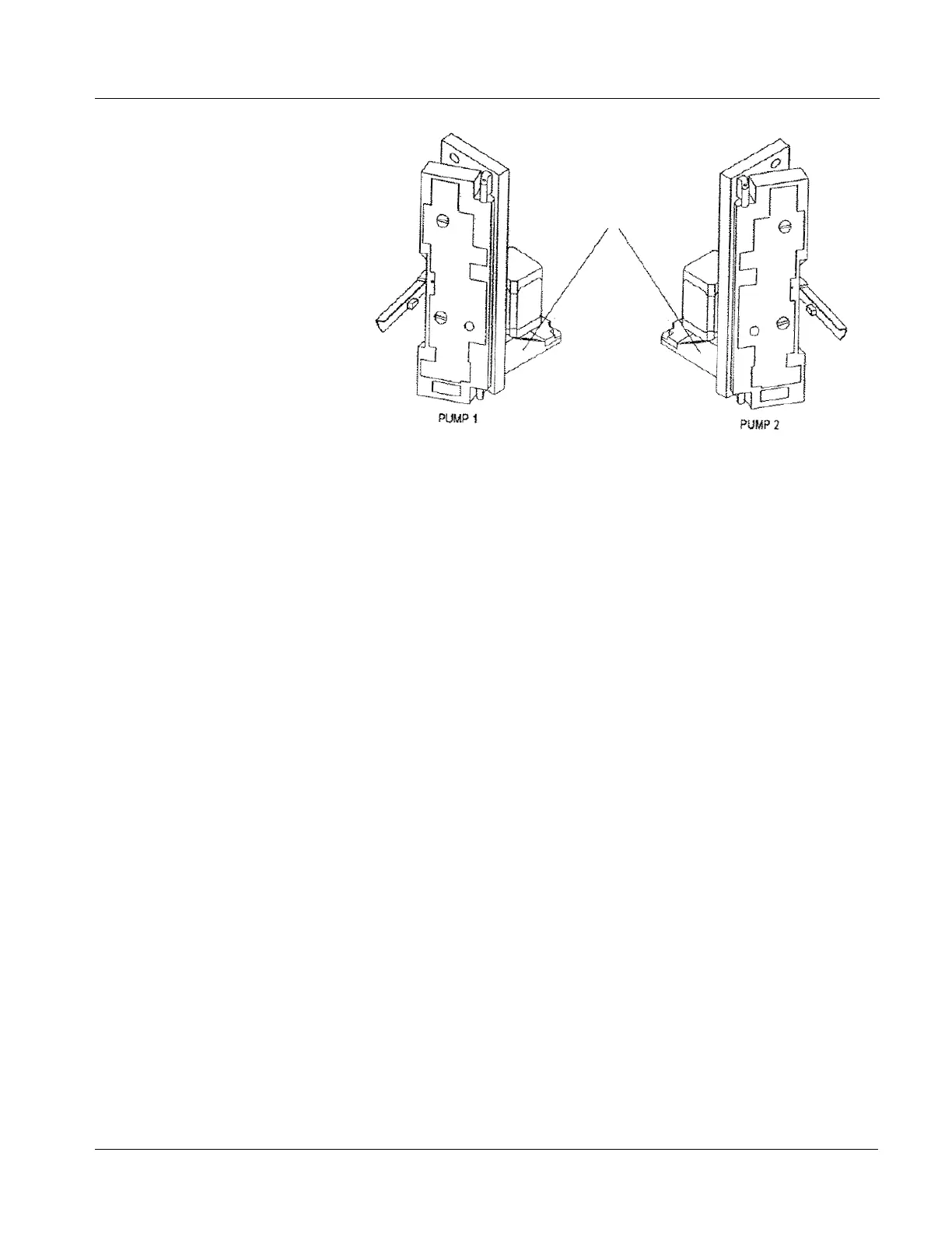
Figure 8-2 Location of Yellow or White Dot
Note: If there is a white dot, the connector is gold. A yellow dot indicates that
Nyogel 759G has already been applied to the ribbon foil.
If no dot is present, complete the following steps:
14.1 Carefully disconnect the slide clamp sensor foil ribbon from
the FPC connector (located between the motor and the base
plate). Use a right angled needle nose plier with the tips
covered with electrical tape or heat shrink tubing. DO NOT
WIGGLE THE RIBBON FOIL DURING REMOVAL.
14.2 Apply a thin coat of Nyogel 759G on the contacts of the ribbon
foil to protect them from oxidation and carefully reinsert it
using the angled needle nose pliers into the connector. DO
NOT WIGGLE THE RIBBON FOIL DURING
INSTALLATION.
14.3 Using a yellow paint pen, mark a yellow dot on the side
(nearest the middle of the device, see Figure 8-2) of the slide
clamp assembly. Proceed to step 15.
15. Connect the flexible cable (Figure 11-9 or Figure 11-14 , item 29) to the
connector on the terminal board.
16. Place the motor holding plate (Figure 11-9 or Figure 11-14 , item 30) on
the motor shaft and slide it in the safety/slide clamp assembly while
replacing the finger and motor assembly.
17. Install the six screws (Figure 11-6 or Figure 11-11 , item 19). Tightening
torque is 6 kgf-cm (5.2 in-lb).
18. Install the two motor holding plate screws (Figure 11-9 or Figure 11-14 ,
item 30). Tightening torque is 6 kgf-cm (5.2 in-lb).