Chapter 15 Technical Drawings
Mini-Switch LB 471
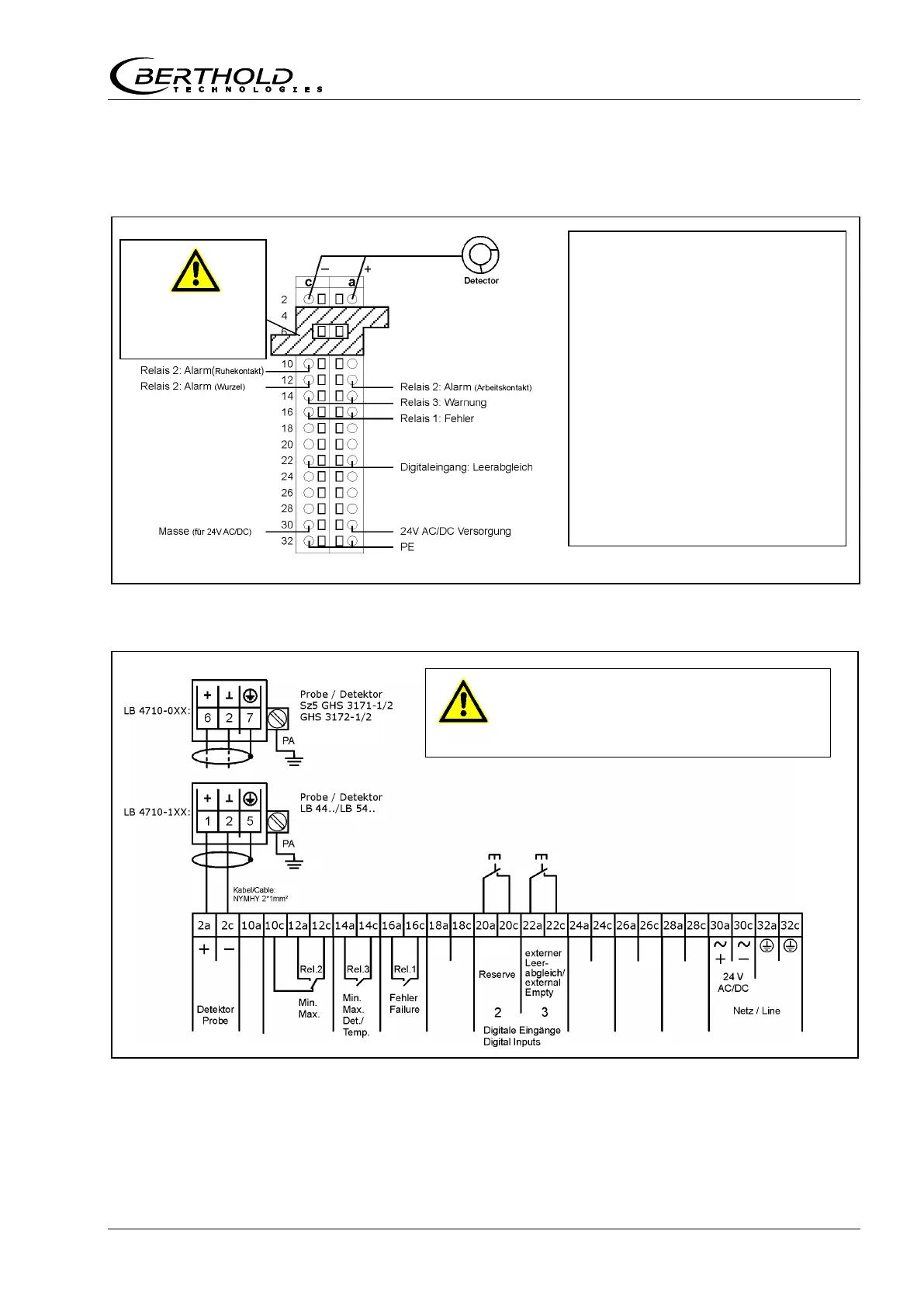
15.6.3 Cassette
Figure 56: Pin assignment of terminal block
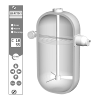
Figure 57: Connection diagram of terminal block
For intrinsically safe installation use
connector sleeves.
Connect wires:
1
Insert suitable screw-driver
into the square hole next to
the terminal. This will open
the terminal and you can in-
sert the wires.
2
Pull the screw-driver out
again. The wire is now
jammed in the spring-finger
connector.
Plastic block must be
mounted for
intrinsically safe in-
stallation.
LB 44..
LB 54..
Sz5 GHS 3171..
GHS 3172..