CFX96 and CFX384 Systems Manual
19
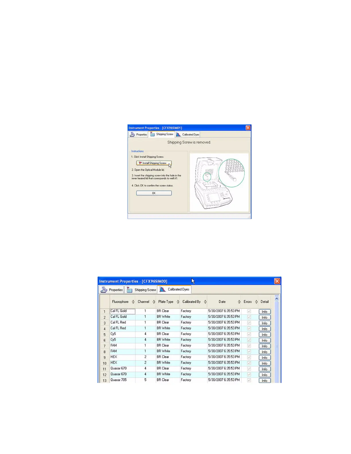
Shipping Screw Tab
The Shipping Screw tab includes instructions for installing or removing the red shipping screw.
To prevent damage to the optical reaction modules, install the shipping screw any time you
ship the CFX96 system or CFX384 system.
NOTE: If the shipping screw is detected by the software, the Instrument Properties
window automatically opens with the Shipping Screw tab in front. Follow the
instructions to remove the screw.
The information in this tab changes depending on whether the shipping screw is installed or
removed. For example, to install the shipping screw, click the Install Shipping Screw button
and follow the instructions in the tab (Figure 21).
Figure 21. Instructions for installing the shipping screw.
Calibrated Dyes Tab
Open the Calibrated Dyes tab to view the list of calibrated fluorophores and plates for the
selected instrument. Click an Info button to see detailed information about a calibration.
Figure 22. Calibrated Dyes tab in the Instrument Properties window.