1 689 975 233 2018-05-08| Robert Bosch GmbH
Repair | EPS 708 | 27 en
458863-12_Ri
1
2
4
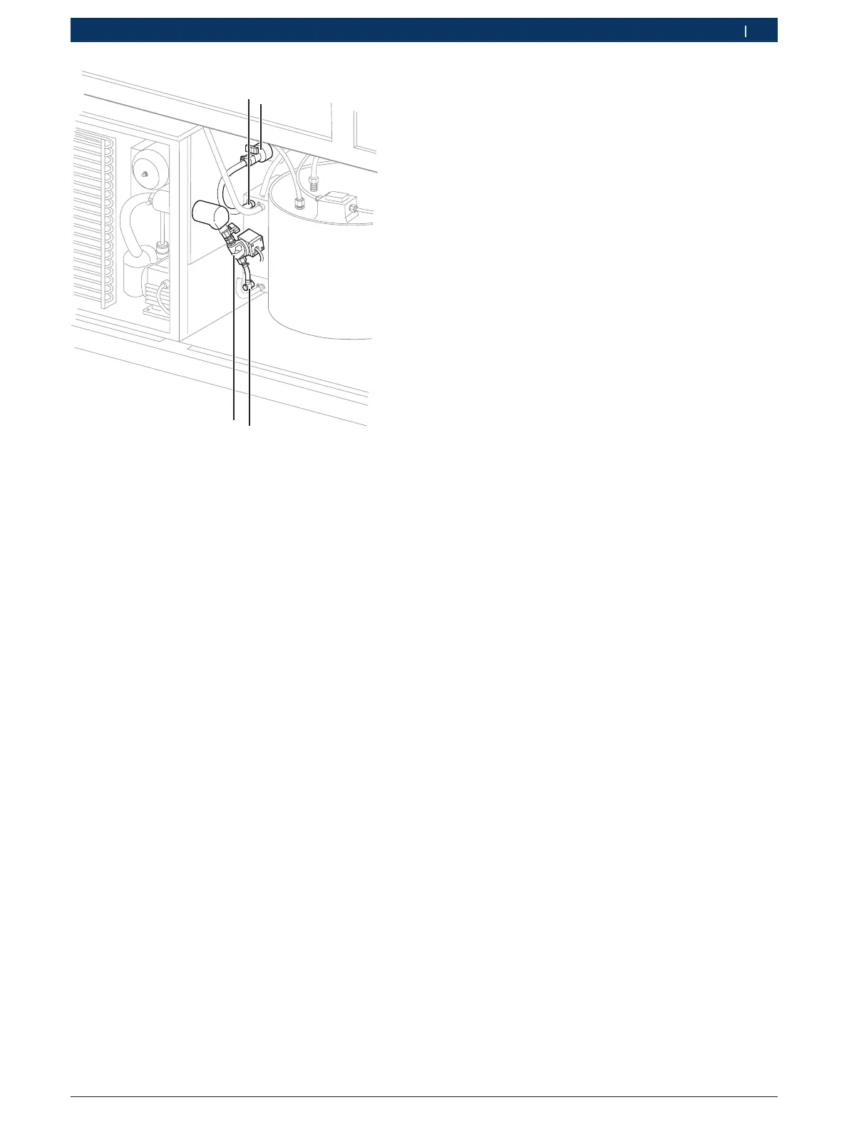
Fig. 40: Removing the chiller
i The hoses still contain residual amounts of cooling
water. Catch these residues.
2. Remove the hoses (see Fig. 40, items 1 and 3) from
the heat exchanger.
3. Slacken all 4 bolts securing the chiller to the
support frame.
! Due to its weight, the assistance of a second person
or use of suitable lifting gear is required to remove
the chiller from the test bench.
4. Pull the chiller out of the support frame at the front
of the EPS 708 test bench, and place on a firm
surface.
5. Remove the control valve from the chiller.
6. Remove piping from the chiller return.
6.7.4 Installing the chiller
! Note the direction of flow when installing the control
valve. It must run from the chiller towards the heat
exchanger.
1. Install the control valve (see Fig. 40, item 4) on the
chiller.
2. Fit the hose (see Fig. 40, item 2) to the chiller
return.
! Due to its weight, the assistance of a second person
or use of suitable lifting gear is required to install
the chiller in the test bench.
3. Push the chiller into the support frame of the
EPS 708 test bench.
4. Secure the chiller to the support frame with bolts.
5. Fit the hoses to the heat exchanger (see Fig. 40).
! Note the direction of air flow when installing the fan.
The air must flow from the outside to the inside.
6. Fit the fan to the chiller with 4 screws.
i Secure loose connecting cables to the support
frame with cable ties.
7. Connect cable 1684463798to the fan via a
distribution block.
8. Connect cables 1 684 463 762 and 1684463727 to
the chiller switch box.