5-36
Confidential
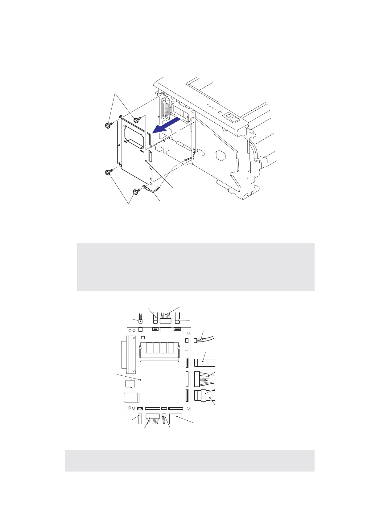
8.8 Main PCB
(1) Remove the four cup S M3x6 SR Taptite screws, remove the FG harness and then
remove the Shield cover.
Fig. 5-34
(2) Disconnect the five or six connectors and six flat cables from the Main PCB.
Fig. 5-35
Note:
• After disconnecting the flat cable(s), check that each cable is not damaged at its
end or short-circuited.
• When connecting the flat cable(s), do not insert it at an angle. After insertion, check
that the cable is not at an angle.
Assembling Note:
• When assembling the Main PCB, ensure to place the Ferrite Core correctly.
Taptite, cup S M3x6 SR
Taptite, cup S M3x6 SR
FG harness
Shield cover
LD harness (Flat cable)
Panel PCB connector
Relay front (Flat cable)
Ferrite core
Wireless PCB connector (Only Wireless LAN
Polygon motor (Flat cable)
LVPS PCB connector
Main motor (Flat cable)
HVPS PCB (Flat cable)
LT connector FAN connector
Main PCB
DX solenoid connector
Relay rear (Flat cable)
 Loading...