5-37
Confidential
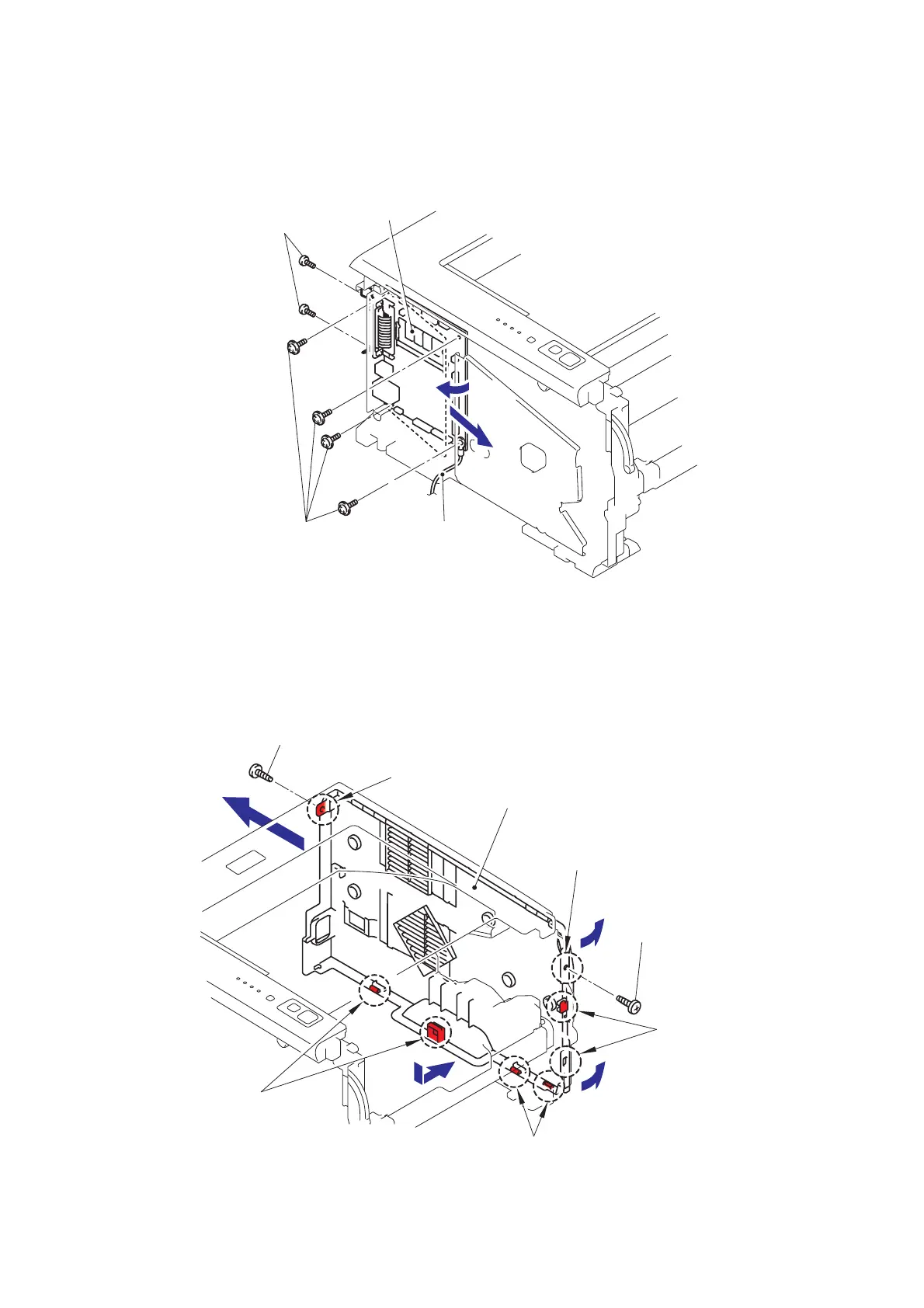
(3) Remove the cup S M3x6 SR Taptite screw, and then remove the FG harness.
(4) Remove the four cup S M3x6 SR Taptite screws and two Screws to remove the Main
PCB by following the direction of 4a and 4b.
Fig. 5-36
8.9 Side Cover R
(1) Remove the two bind B M4x12 Taptite screws, and then remove the Side cover R by
following the direction from 1a to 1d.
Fig. 5-37
Main PCB
Taptite, cup S M3x6 SR
FG harness
Screws
4a
4b
Taptite, cup S M3x6
Taptite, cup S M3x6
Hook
Hook
Hooks
Hooks
Hooks
Side cover R
1d
1c
1a
1b
 Loading...