5-45
Confidential
8.11.2
Panel PCB ASSY
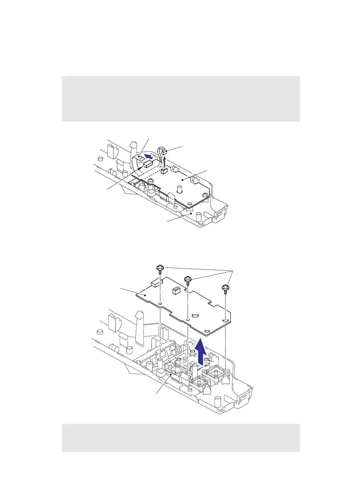
(1) Disconnect the Back light PCB harness from the LCD panel PCB ASSY.
(2) Release the Lock, and then remove the LCD panel PCB harness.
Fig. 5-48
(3) Remove the three cup B M3x8 Taptite screws, and then remove the LCD panel PCB
ASSY.
Fig. 5-49
Note:
• After disconnecting the flat cable(s), check that each cable is not damaged at its end or
short-circuited.
• When connecting the flat cable(s), do not insert it at an angle. After insertion, check that
the cable is not at an angle.
Assembling Note:
• When assembling the LCD panel PCB ASSY, secure the screws according to the order
of alphabet described in the figure above.
LCD panel PCB harness
(Flat cable)
Back light PCB harness
LCD panel PCB ASSY
Top cover printed ASSY
Lock
a
b
c
Taptite, cup B M3x8
LCD panel PCB ASSY
Top cover printed ASSY
 Loading...