3-111
Confidential
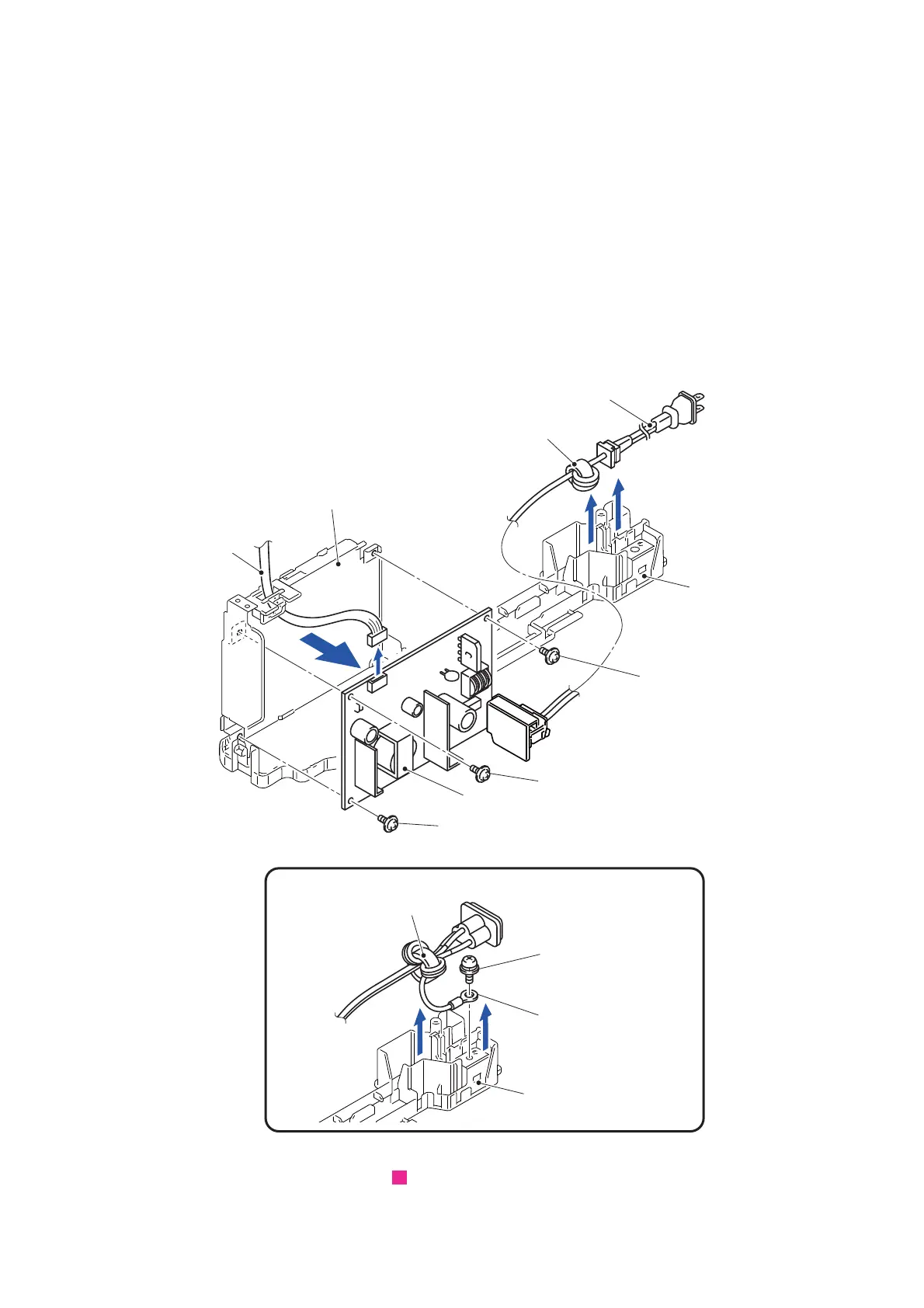
(4) Remove the screw (SCREW PAN (S/P WASHER) M3.5x6) and remove the AC
cord FG wire. (Case of 200 V)
Assembling Note: After connecting the AC cord FG wire, be sure to check that there
is no looseness of the wire.
(5) Remove the Power cord and Ferrite core from the Enclosure base.
Assembling Note: When handling the Power cord, be sure to check the sheath is not
damaged.
(6) Remove the three screws (SCREW CUP M3x6) and remove the Power supply
PCB ASSY from the Power supply unit.
Assembling Note: Two insulation sheets must be interleaved without damage
between the Power supply PCB ASSY and Power supply unit.
(7) Remove the Power supply harness from the Power supply PCB ASSY.
Fig. 3-135
Routing of harnesses: See “ Power supply PCB ASSY”.
Power cord
Ferrite core
SCREW CUP M3x6
Power supply PCB ASSY
SCREW CUP M3x6
Power supply harness
Power supply unit
Enclosure base
5
5
6
7
SCREW CUP M3X6
Enclosure base
Ferrite core
<Case of 200V>
4
4
SCREW PAN
AC cord FG wire
(S/P WASHER) M3.5x6
14
 Loading...