3-78
Confidential
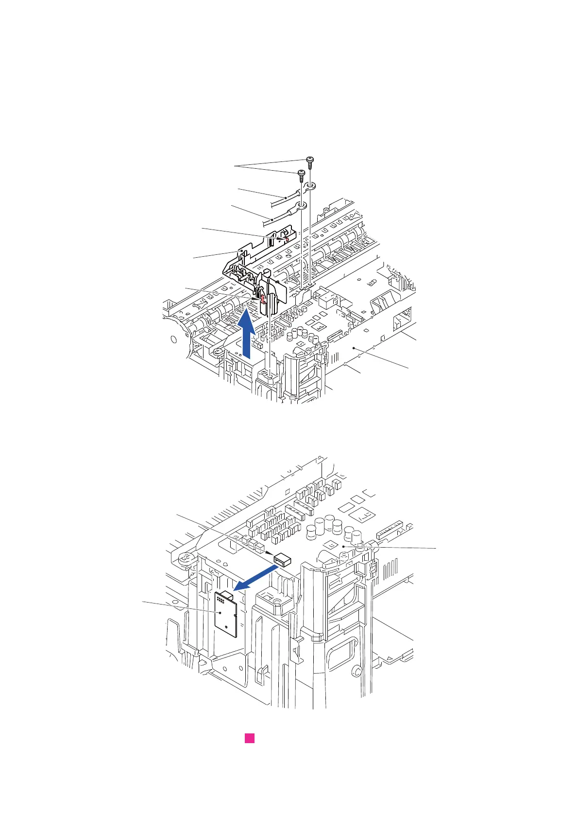
(3) Remove the screw (SCREW BIND M3x6) and remove the Tray FG wire (T1).
(4) Remove the screw (SCREW BIND M3x6) and remove the Tray FG wire (LT).
(5) Release all the wiring attached to the Main PCB harness hold L.
(6) Release the two Hooks and remove the Main PCB harness hold L from the Lower
cover.
Fig. 3-80
(7) Remove the Wireless LAN PCB from the Connector (CN15) of the Main PCB.
Fig. 3-81
Routing of harnesses: See “ Main PCB”.
Main PCB harness hold L
Hook
Hook
Lower cover
Tray FG wire (T1)
Tray FG wire (LT)
SCREW BIND M3x6
Wireless LAN
PCB
CN15
Main PCB
4
 Loading...