S-7300A
Lowest position of
needle
bar
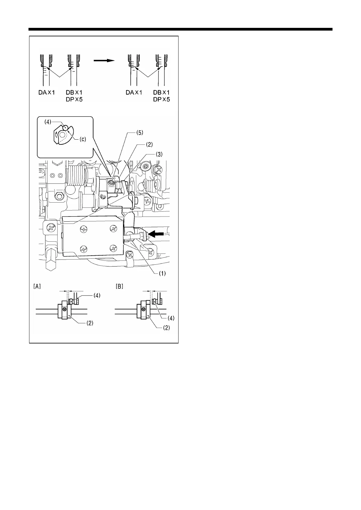
<Thread trimming cam position adjustment>
1.
Raise the needle bar 5 mm from its lowest position so that
the reference line (b) is aligned with the bottom edge of
the needle bar bush, and then push the plunger (1) of the
thread trimmer solenoid in the direction of the arrow with
your finger.
Adjust the position of the thread trimmer cam (2) at this
time so that the roller shaft (4) of the thread trimming cam
lever assembly (3) touches the hollow (c) of the thread
trimmer cam (2) and so that the clearance between the
edge of the thread trimmer (2) and the roller (4) is 0.5 to
1.0 mm, and then tighten the set screw (5). (Fig. [A])
2. Check that the edge of the thread trimmer cam (2) and
the roller shaft (4) do not touch when the roller shaft (4)
returns to the right. (Fig. [B])
* Tighten the two set screws (5) to approximately 4 N.m.
Direction of cam
rotation
b)
0.5mm - 1.0mm