144
Type 8692, 8693
english
DeviceNet
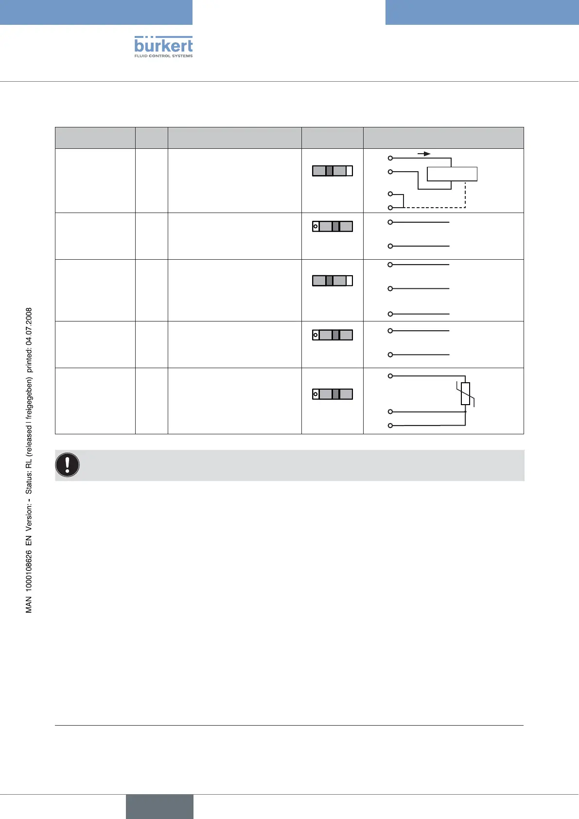
6.5 Process Actual Value (M 8 Round Plug)
Input type* Pin Configuration Switch** External circuit
4 – 20 mA
- internally supplied
1
2
3
4
+ 24 V transmitter supply
Output from transmitter
GND
Bridge after GND (GND from
3-wire transmitter)
Switch on
left
GND
1
2
3
4
Transmitter
I
4 – 20 mA
- externally
supplied
1
2
3
4
not assigned
Process actual +
not assigned
Process actual -
Switch on
right
2
4 GND
4 ... 20 mA
Frequency
- internally supplied
1
2
3
4
+ 24 V sensor supply
Clock input +
Clock input - (GND)
not assigned
Switch on
left
1
2
3
+ 24 V
Clock +
Clock -
Frequency
- externally
supplied
1
2
3
4
not assigned
Clock input +
Clock input -
not assigned
Switch on
right
2
3 Clock -
Clock +
Pt 100
(see information
below)
1
2
3
4
not assigned
Process actual 1 (current feed)
Process actual 2 (GND)
Process actual 3 (compensation)
Switch on
right
Pt 100
2
3
4
For reasons of wire compensation connect the Pt 100 sensor via 3 wires.
Always bridge PIN 3 and PIN 4 on the sensor.
6.6 Terminating Circuit for DeviceNet Systems
When installing a DeviceNet system, ensure that the terminating circuit of the data lines is correct. The circuit prevents the oc-
currence of interference caused by signals reflected onto the data lines. The trunk line must be terminated at both ends with
resistors of 120 Ω each and 1/4 W power loss.
(see figure 4: Network topology, DeviceNet)
* Can be adjusted by software.
** The switch is situated behind the srew (see Fig. “Connection of DeviceNet-8693”).