46
Type 8692, 8693
english
Installation
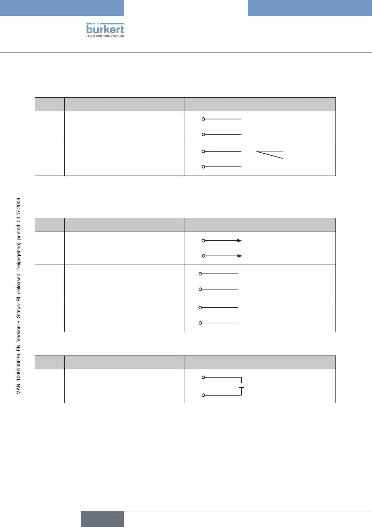
5.2 Terminal Assignment for Cable Gland - Position Controller Type 8692
5.2.1 Input Signals from the Control Centre (e.g. PLC)
Terminal Configuration External circuit
11
10
Set-point value +
Set-point value GND
11
10 GND
+ (0/4 – 20 mA or 0 – 5 / 10 V)
12
13
Binary input + (optional only)
Binary input GND (optional only)
12
13 GND
+ 0 – 5 V (log. 0)
10 – 30 V (log. 1)
5.2.2 Output signals to the control centre (e.g. PLC)
(required for Analogue output and/or Binary output option only)
Connect the terminals according to the design (options) of the positioner. →
Terminal Configuration External circuit
9
8
Analogue position feedback +
Analogue position feedback GND
9
8 GND
+ (0/4 – 20 mA or 0 – 5 / 10 V)
completely galvanically isolated
5
6
Binary output 1
Binary output GND
5
6 GND
24 V / 0 V NC / NO
7
6
Binary output 2
Binary output GND
7
6 GND
24 V / 0 V NC / NO
5.2.3 Operating Voltage
Terminal Configuration External circuit
14
13
Operating voltage +
Operating voltage GND
14
13
24 V DC ± 10 %max.
residual ripple 10 %
When the power supply voltage is applied, the positioner is operating.
Now implement the required basic settings and activate automatic adjustment of the positioner as described in the chapter
→
entitled “Initial Start-up” or “Starting and Setting Up the Position Controller Type 8692”.