168
Type 8692, 8693
english
General Rules - Appendix
1 SELECTION CRITERIA FOR CONTINUOUS VALVES
The following criteria are crucial for optimum control behaviour and to ensure that the required maximum flow is reached:
the correct selection of the flow coefficient which is defined primarily by the nominal width of the valve;•
close coordination between the nominal width of the valve and the pressure conditions in consideration of the remaining flow •
resistance in the equipment.
Design guidelines can be given on the basis of the flow coefficient (k
V
value). The k
V
value refers to standardised conditions with
respect to pressure, temperature and media properties.
The k
V
value describes the flow rate of water through a component in m³/h at a pressure difference of Δp = 1 bar and
T = 20 °C.
The “k
VS
value” is also used for continuous valves. This indicates the k
V
value when the continuous valve is fully open.
Depending on the specified data, it is necessary to differentiate between the two following cases when selecting the valve:
a) The pressure values p1 and p2, known before and after the valve, represent the required maximum flow Q
max
which is to be reached:
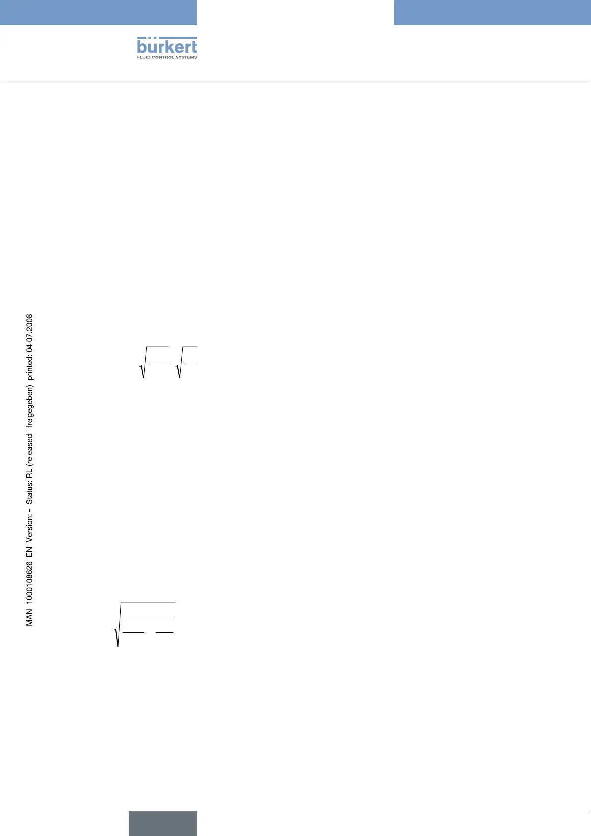
The required k
VS
value is calculated as follows:
(1)
p
p
Qk
0
0
max
s v
ρ
ρ
⋅
Δ
Δ
=
⋅
Meaning of the symbols:
k
VS
flow coefficient of the continuous valve when fully open [m³/h]
Q
max
maximum volume flow rate [m³/h]
Δp
0
= 1 bar; pressure loss on the valve according to the definition of the k
V
value
ρ
0
= 1000 kg/m³; density of water (according to the definition of the k
V
value)
Δp pressure loss on the valve [bar]
ρ density of the medium [kg/m³]
b) The pressure values, known at the input and output of the entire equipment (p
1
and p
2
), represent the required maximum
flow Q
max
which is to be reached:
1st step: Calculate the flow coefficient of the entire equipment k
Vges
according to equation (1).
2nd step: Determine the flow rate through the equipment without the continuous valve
(e.g. by "short-circuiting" the line at the installation location of the continuous valve).
3rd step: Calculate the flow coefficient of the equipment without the continuous valve (k
Va
) according to equation (1).
4th step: Calculate the required k
VS
value of the continuous valve according to equation (2):
(2)
²k
1
²k
1
1
k
a VVges
s v
−
=