Chapter 7
7-5
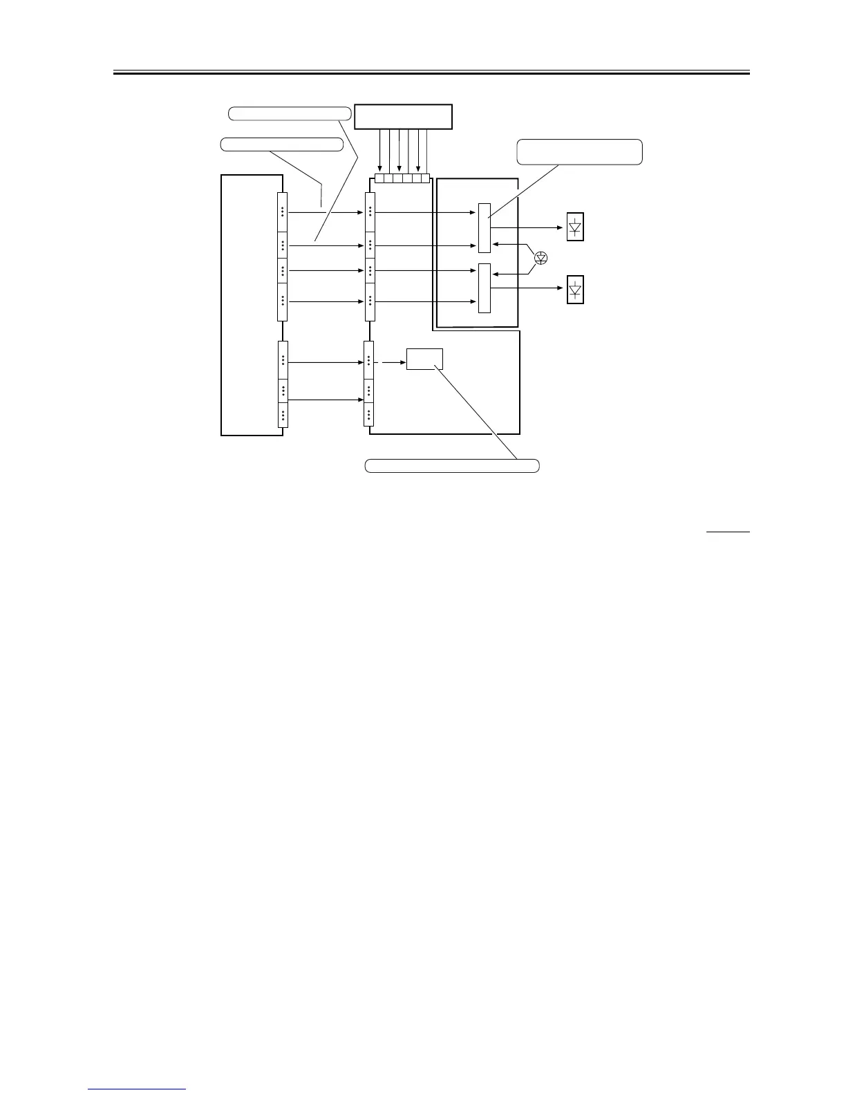
F-7-6
7.3.2.2 Controlling Laser Activation
0006-9518
iR105i/iR105+ / iR9070 / iR85+ / iR8070
The following figure shows the construction of the system used to control laser activation.
Image processor PCB
J1106
J1107
J1354
J1353
1
16
17
20
21
24
25
40
VIDEO-B
VIDEO-A
CLK-B
CLK-A
Image signals for the laser B
Laser driver PCB 2
Laser driver PCB 1
1
2
3
4
5
6
Relay PCB
Clock pulses for the laser B
10
18
1
9
10
18
1
9
19
30
1
16
17
20
21
24
25
40
Light intensity
control signal
Activation control
signal
5V
8V
-8V
GND
GND
GND
J1301
J1714
LD-BLD-A
Laser B
Laser A
Intensity monitor
EEPROM
[1]
The laser diode is turned on
to suit the image signal.
19
30
[2]
VR for image area activation adjustment

 Loading...