Chapter 10
10-31
F-10-86
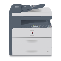
10.5.9.4 Mounting the Main/Sub Heater
0008-8194
/ iR85+ / iR8070
To mount the fixing heater, reverse the steps used to remove it with the
following in mind:
a. Do not touch the surface of the heater.
b. For both, mount the heater so that the side with the longer harness is
to the front.
c. Viewing from the front of the fixing assembly, mount the main heater
[1] to the right and the sub heater [2] to the left.
F-10-87
10.5.9.5 Points to Note When Mounting the Fixing Heater
0008-4620
iR105i/iR105+ / iR9070
1. Do not touch the heater surface.
2. For both heaters, mount so that the side with the longer heater harness
is toward the front.
3. Viewing from the front of the fixing assembly, mount the main heater
on the right (for 200V model, 1150 W; for 208V model, 1220 W; for
230V model, 1185 W) and the sub heater on the left (for 200V model,
565 W; for 208V model, 600 W; for 230V model, 645 W).
4. Viewing from the rear, connect the right side of the faston of the
heater at the rear to the main heater, and connect the top side to the
sub heater.
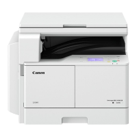
Height of the Fixing Inlet Guide
F-10-88
Do not loosen the fixing screw on the inlet guide, as you will have to
adjust the position of the inlet guide if you remove the inlet guide base.
If you must loosen it, be sure to adjust the position of the inlet guide
afterward by referring to the index on the fixing assembly.
10.5.9.6 Points to Note When Mounting the Fixing Heater
0008-8435
/ iR85+ / iR8070
1. Do not touch the surface of the heater directly.
2. For both heaters, be sure that the side with the longer heater wire is
toward the front.
3. When viewing from the front, mount the main heater (1000 W for
100V model; 900 W for 208V model; 965W for 230V model) on the
right and the sub heater (400 W for 100V model; 600 W for 208V
model; 645W for 230V model) on the left.
4. When viewing from the rear, connect the faston for the heater at the
rear so that the right side is to the main heater and the top side is to
the sub heater.
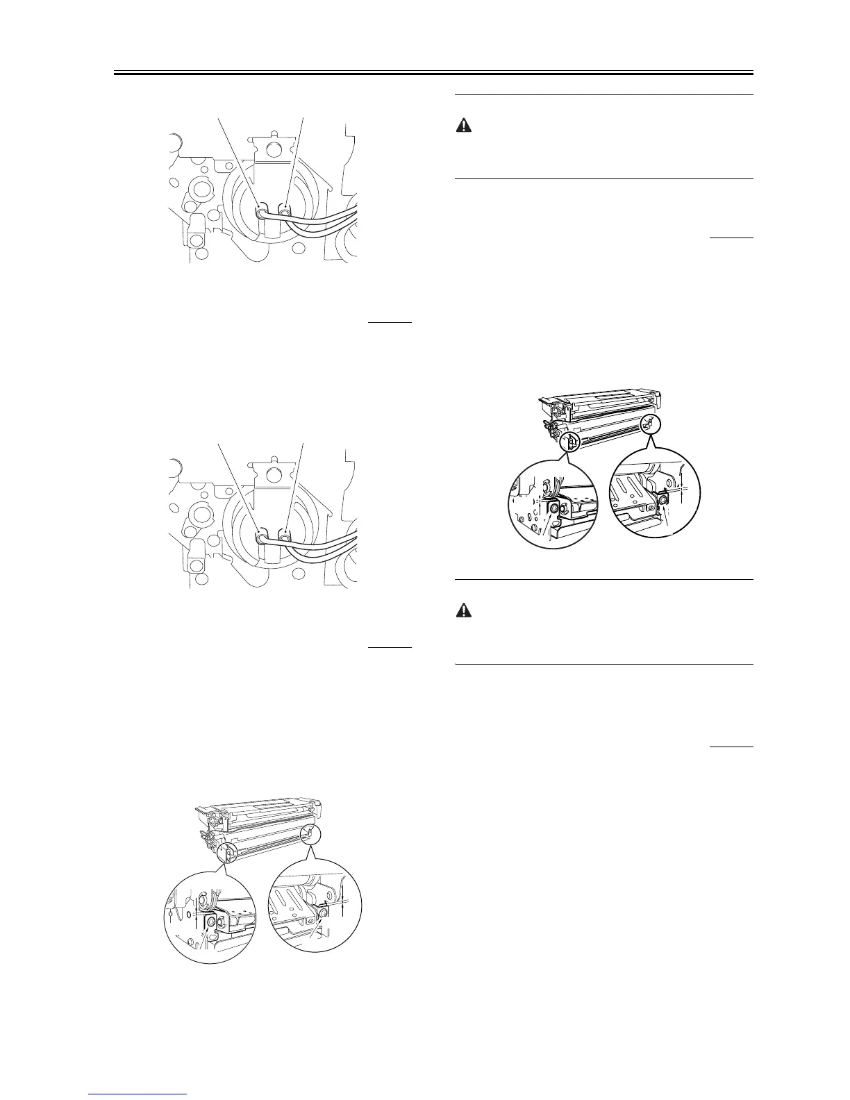
Height of the Fixing Assembly Inlet Guide
F-10-89
If you should remove the inlet guide base, you will have to adjust the
position of the inlet guide. Do not loosen the fixing screw on the inlet
guide. If you must, be sure to put it back to its original position with
reference to the scale on the fixing assembly base.
10.5.10 Fixing Cleaning Belt
10.5.10.1 Removing the Fixing Cleaning Belt
0007-1471
iR105i/iR105+ / iR9070 / iR85+ / iR8070
1) Slide the fixing/feeding unit halfway out; then, release the stoppers on
both rails, and slide the unit farther out.
2) Remove the pre-transfer charging assembly cover, fixing feeding unit
releasing lever, and fixing roller knob.
3) Remove the screw [1], and detach the fixing assembly upper cover
[2].
[2]
[1]
[2]
[1]
5.8mm
(reference only)
5.8mm
(reference only)
Fixing screw
Fixing screw
5.8mm
(reference
only)
5.8mm
(reference
only)
Fixing
screw
Fixing
screw

 Loading...