Chapter 8
8-11
F-8-14
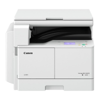
8.3.8 Determining the Optimum Developing Bias
0006-9613
iR105i/iR105+ / iR9070 / iR85+ / iR8070
An optimum developing bias (Vdc) is computed based on the optimum drum surface potential (VD).
F-8-15
8.3.9 Potential Control for Transparency Mode
0006-9615
iR105i/iR105+ / iR9070 / iR85+ / iR8070
To prevent detachment of toner in high density areas on transparencies, the contrast is decreased to limit the amount of toner deposit. To enable the decrease
in contrast, potential control for transparency mode is executed to select a target value.
WMUPR
WMUP
STBY
195˚C
200˚C
Potential sensor
Developing bias
(DC)
Laser
-10% -20%
Pw Pw1 Pw2 Pw3
Pw8
VL1
VL1 VL2 VL3 VL8
VL-NG
VL-NG
VL2
VL3
Target VL
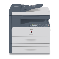
Measurement is continued by varying the
level of the laser output so as to attain
the target VL.
If the measurement is identical to the
target VL, control is ended.
Measurements are taken as many
as 8 times; at times, an approximate
(to the target VL) may be used.
Corrective control sequence
started
The laser output needed to
attain the target VL is
determined.
Reference
output
WMUPR
WMUP
STBY
195˚C
200˚C
Potential sensor
Potential determined
Laser
Grid bias
Vg
Vg
Pw
Pw
Potential control sequence started
VD VL
Vdc
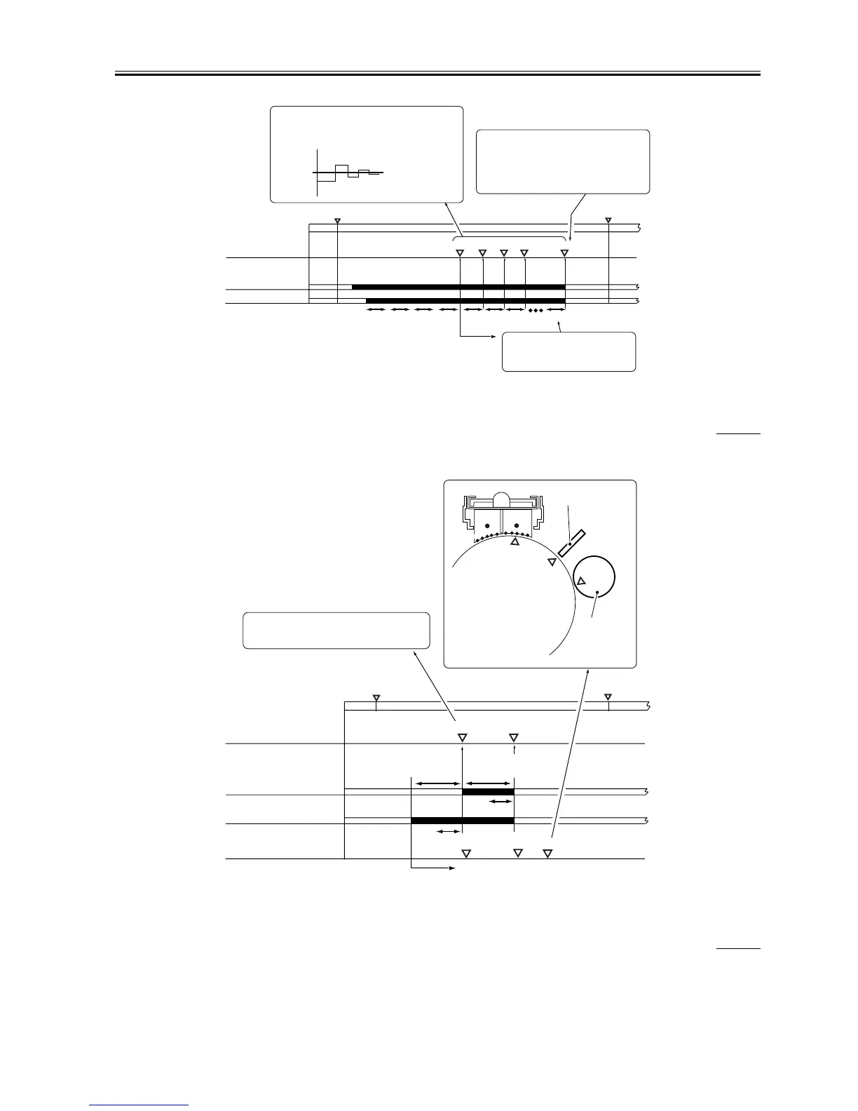
Vdc is computed based on this VD;
Vdc = VD - Vback (120 V)
Optimum grid
bias determined
Vg
VD
Vdc
Photosensitive drum
Potential sensor
Developing
cylinder
Optimum laser output
determined

 Loading...