Chapter 8
8-18
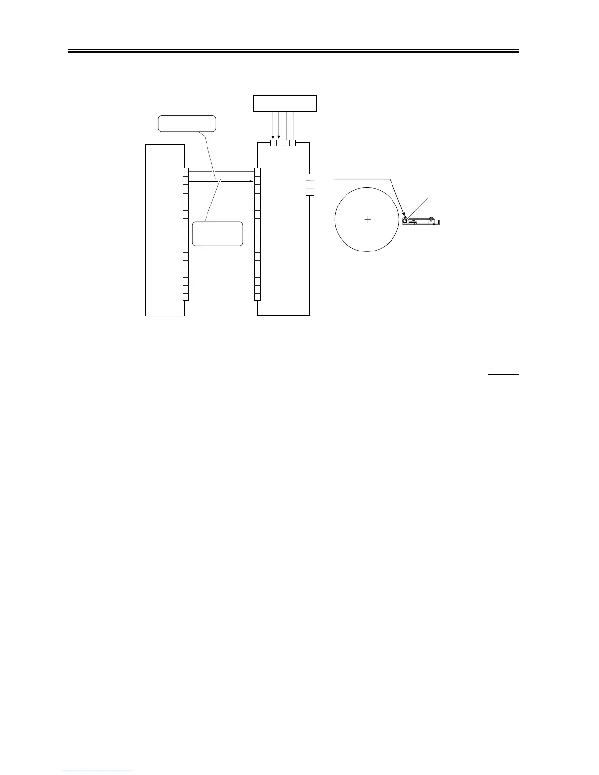
The dust-collecting roller bias mechanism is controlled for the following:
[1] Turning on and off the dust-collecting roller bias.
Figure shows the construction of the dust-collecting roller bias control system.
F-8-26
8.4.3 Pre-Transfer Charging Mechanism
8.4.3.1 Outline
0006-9697
iR105i/iR105+ / iR9070 / iR85+ / iR8070
The pre-transfer charging mechanism is controlled for the following:
[1] DC bias constant current
[2] AC bias constant voltage
[3] Output to suit the environment (fuzzy control)
Figure shows the construction of the pre-transfer charging control system.
DC controller PCB
J510A
DC 1000V
J723
1
2
3
4
5
6
7
8
9
10
11
12
13
14
15
16
1
2
3
4
5
6
7
8
9
10
11
12
13
14
15
16
0 V
24 VH
24 VH
HVDC-EN
GND
GND
1
2
3
4
Relay PCB
Dust-collecting
roller
J732
1
2
3
High-voltage DC PCB
When '1', high-voltage
output is ready.
When '1',
the dust-collecting
roller bias turns on.

 Loading...