Chapter 9
9-41
F-9-48
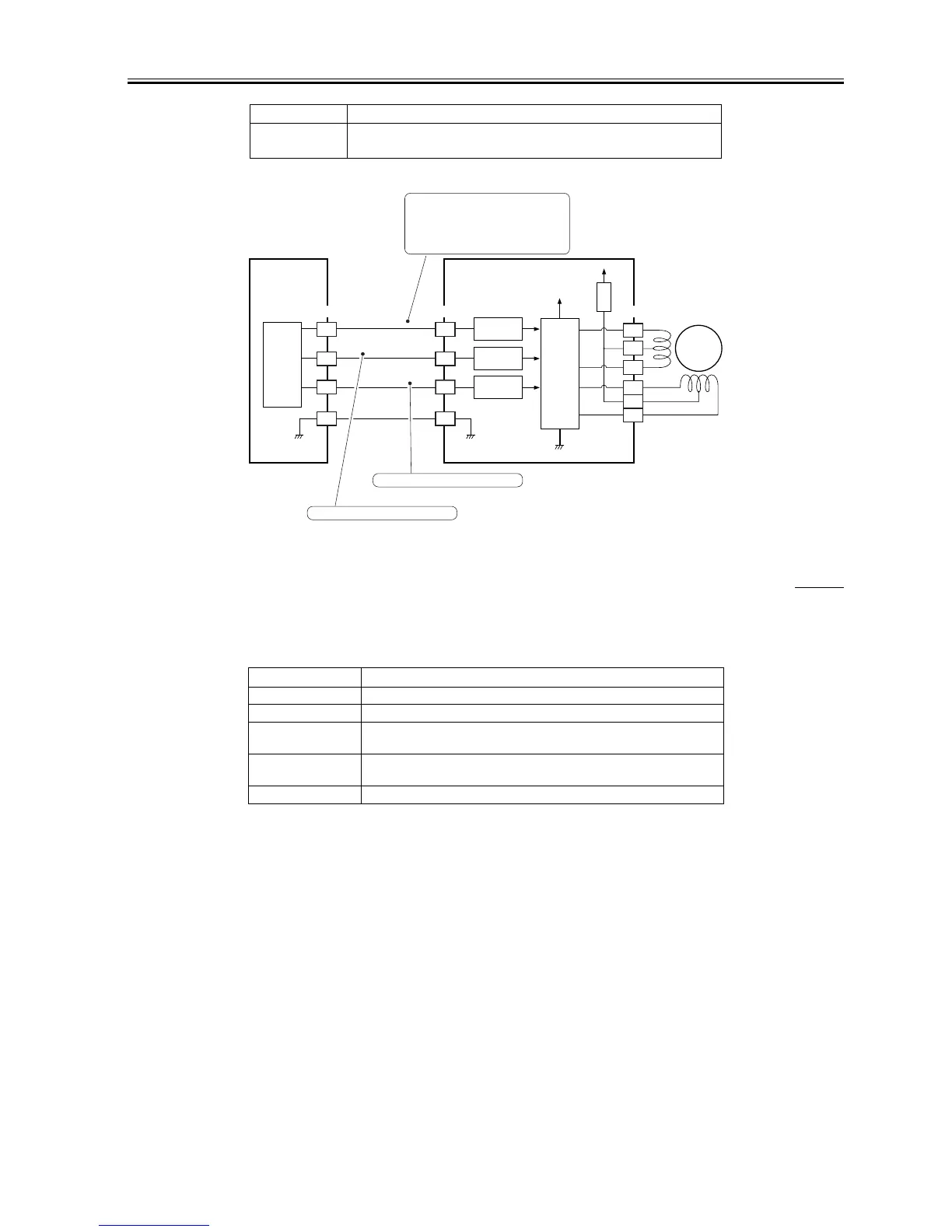
9.8.8 Controlling the duplexing feeder motor (M12)
0007-0498
iR105i/iR105+ / iR9070 / iR85+ / iR8070
Table shows the functions of the duplexing feeder motor control circuit, and Figure is a block diagram of the circuit.
T-9-32
Error detection No error code; however, if a fault in the drive of the motor, a jam will
occur.
Item Description
Power supply 24 V is supplied by the no-stacking feeding driver PCB.
Drive signal Signal (DUPF_OFF) from the DC controller PCB.
Operating/drive
assembly
See Figure.
Control ON/OFF control
Rotation control
Error detection No error code; however, a fault in the motor drive will cause a jam.
Item Description
Motor
driver
(IC1)
+24V
+24V
A
A*
B
B*
M11
A9
A11
A8
A7
A10
A6
FU3
Interface
circuit
Interface
circuit
Interface
circuit
A5
A6
A7
A8
A8
A7
A6
A5
J3602J519 J3603
DUPI-OFF
DUPI-B
DUPI-A
DC controller
PCB
No-stacking feeding
driver PCB
CPU
(IC13)
Phase B excitation control signal
Phase A excitation control signal
When the M11 drive signal goes '1',
the pickup motor starts to rotate.
When the M11 drive signal goes '0',
the pickup motor stops.

 Loading...