Chapter 14
14-38
F-14-83
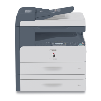
8) Connect the cable [1] of the potential sensor checking electrode to the
frame (GND) [2] of the machine.
Be sure to allow enough space from the sensor window so that the clip
will never come into contact with the sensor cover.
F-14-84
9) Fit the door switch actuator into the door switch assembly.
10) Turn on the power switch.
After turning on the power switch, do not touch the potential sensor
assembly.
11) Make the following selections in service mode, and check to see that
the reading for initial rotation is between 0 and 30:
COPIER>DISPLAY>DPOT>DPOT-K.
MEMO:
1. If the reading in method 1 is as indicated but the reading in method 2
is not as indicated,
Suspect dirt on the sensor or a fault in the potential measurement unit.
2. If the readings in both methods 1 and 2 are as indicated,
It is safe to assume that the operation and the signal path from the
potential sensor unit to the microprocessor on the DC controller PCB are
normal.
12) Turn off the power switch.
13) Detach the potential sensor checking electrode.
14) Mount the potential sensor support plate.
15) Turn on the power switch.
14.7.14 When Replacing the Potential Sensor/
Potential Control PCB
0007-0705
iR105i/iR105+ / iR9070
1) Check to make sure that the Execute/Memory lamp in the control
panel is OFF, and turn off the main power switch.
2) Disconnect the power plug from the power outlet.
The machine remains powered after the main power switch is turned off
as long as the power plug is connected to the power outlet. Be sure to
disconnect the power plug from the power outlet.
3) Replace the potential sensor/potential control PCB.
The potential sensor and the potential control PCB are adjusted as a pair.
Be sure to replace them at the same time.
4) Remove the developing assembly, and slide out the process unit.
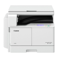
5) Disconnect the connector [1] of the potential sensor.
F-14-85
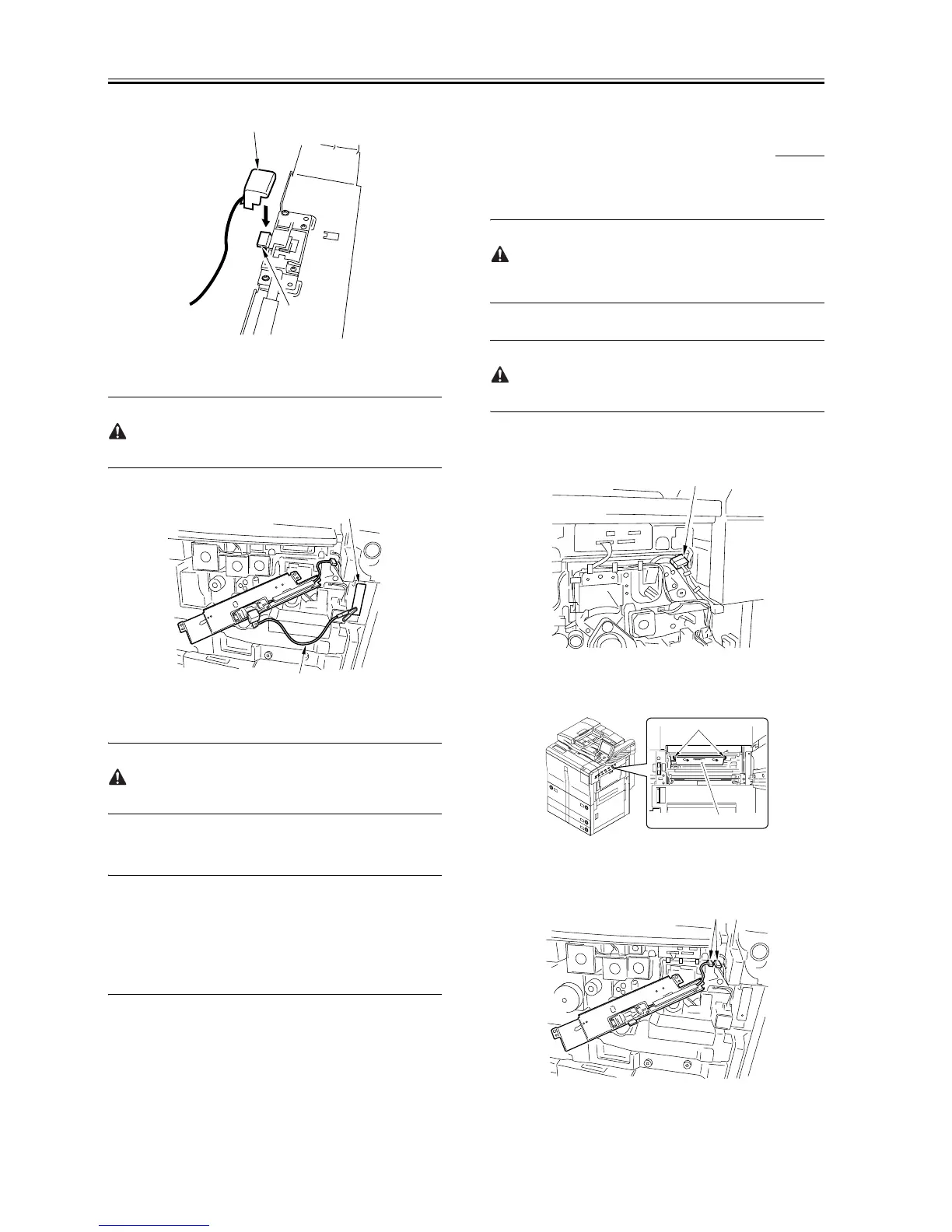
6) Remove the 2 screws [1], and detach the potential sensor support
plate [2].
F-14-86
7) Put back the developing assembly and the process unit.
8) Connect the connector [1] of the potential sensor.
F-14-87
[1]
[2]
[1]
[2]
[1]
[2]
[1]
[1]

 Loading...