28 Connections CG Drives & Automation 01-5980-01r2
Example 5: Reverse current brake wiring
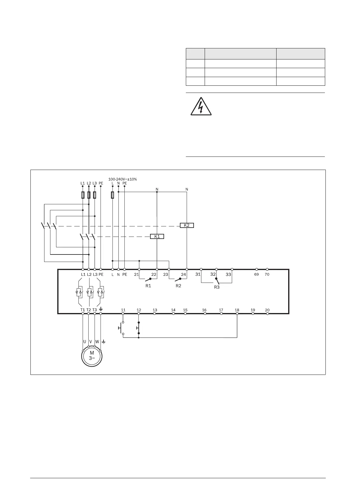
The example in Fig. 24 shows the wiring for a reverse
current brake functionality. For further settings, see the
description for “Braking Method [344]” on page 95.
The contactors have to be controlled by the relay outputs of
the softstarter. For relay settings, see menu [550] and Fig. 63,
page 113. The relay (R1) for the first mains contactor (K1) is
set to “RunSignalFWD” in menu [551], and will control the
mains contactor (K1). The second mains contactor (K2) is
controlled by relay (R2), that is set to “RevCurrBrake” in
menu [552]. During start and full voltage operation the first
contactor (K1) will be activated. For braking R1 will open
and contactor (K2) will be activated via R2 to change the
phase sequence.
Fig. 24 Reverse current brake wiring example.
Menu Description Setting
344 Brake Method RevCurrBrk
551 Relay 1 (terminals 21 and 22) RunSignalFWD
552 Relay 2 (terminals 23 and 24) RevCurrBrake
WARNING!
If configured according to the description,
relays R1 and R2 will never be activated at
the same time. There is an adjustable time
delay (set in menu [346]) for the change-over between
the relays. However, if the relays are not configured
properly, they may be activated at the same time. By
having electrical interlocking between the contactors,
this risk is avoided.
DigIn 1 DigIn 2 +10 V AnIn GND DigIn 3 DigIn 4 +24 V AnOut +24 V
Relay 1 Relay 2 Relay 3
Run FWD Stop
PTC

 Loading...